Version 2.0 and later Owner’s Manual (this document) Read this first. It explains the basic things you need to know in order to use the V-1HD. PDF Manual (download from the Web) 55Remote Control Guide This manual covers remote control of the V-1HD via MIDI. To obtain the PDF manual 1. Enter the following URL in your computer. https://proav.roland.com/ I 2. Go to the V-1HD product page and click the “Support.” Before using the V-1HD, ensure that its system program is at the most recent version.
Contents USING THE UNIT SAFELY. . . . . . . . . . . . . . . . . . . . . 3 IMPORTANT NOTES. . . . . . . . . . . . . . . . . . . . . . . . . . 5 Panel Descriptions . . . . . . . . . . . . . . . . . . . . . . . . . . 6 Top Panel/Front Panel . . . . . . . . . . . . . . . . . . . . . . . 6 Rear Panel (Connecting Your Equipment). . . . . . . 8 Side Panel (Connecting Your Equipment). . . . . . . 10 Basic Operation. . . . . . . . . . . . . . . . . . . . . . . . . . . . . 11 Turning the Power On and Off . . .
USING THE UNIT SAFELY About WARNING and CAUTION Notices Used for instructions intended to alert the user to the risk of death or severe injury should the unit be used improperly. Used for instructions intended to alert the user to the risk of injury or material damage should the unit be used improperly. * Material damage refers to damage or other adverse effects caused with respect to the home and all its furnishings, as well to domestic animals or pets.
USING THE UNIT SAFELY WARNING CAUTION Do not allow foreign objects or liquids to enter unit; never place containers with liquid on unit Disconnect the power plug whenever the unit will not be used for an extended period of time Do not place containers containing liquid (e.g., flower vases) on this product. Never allow foreign objects (e.g., flammable objects, coins, wires) or liquids (e.g., water or juice) to enter this product.
IMPORTANT NOTES Power Supply • Do not connect this unit to same electrical outlet that is being used by an electrical appliance that is controlled by an inverter or a motor (such as a refrigerator, washing machine, microwave oven, or air conditioner). Depending on the way in which the electrical appliance is used, power supply noise may cause this unit to malfunction or may produce audible noise.
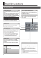
Panel Descriptions Top Panel/Front Panel [OUTPUT FADE] knob p. 20 This performs a fade-in or fade-out for the output video. Turning the control clockwise applies a white fade. Turning it counterclockwise applies a black fade. The indicators on the left and right of the [OUTPUT FADE] knob show the status of the fade. Flashing Dark Fade-in/fade-out in progress Normal output EFFECTS A/EFFECTS B [ON] buttons p. 21 These turn effects on and off for the respective output video on bus A and bus B.
Panel Descriptions HDCP indicator p. 15 This lights up, flashes, or goes dark according to HDCP (digital content protection) settings and the connection status of HDCP-compatible equipment. [BPM SYNC] button p. 18 This turns the BPM sync function on and off. When this is turned on (lighted), the video on bus A and bus B is switched in synchronization with the BPM setting. p. 12, 16 A/B fader This functions as a T-Bar video fader. This performs switching between the bus A video and the bus B video.
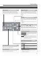
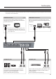
Panel Descriptions Rear Panel (Connecting Your Equipment) * To prevent malfunction and equipment failure, always turn down the volume, and turn off all the units before making any connections. * Be sure to use cables and adaptor plugs with the proper connectors matching those of the other devices you are using. USB port p. 29 You use dedicated software to operate the V-1HD remotely from a connected computer or tablet. OUTPUT connector This outputs the video mixing result (main output video).
Panel Descriptions * The V-1HD is designed to radiate heat from the entire rear panel. Accordingly, the rear panel might become hot during use, but this is not a malfunction. PREVIEW connector p. 15 This outputs the incoming video on channels 1 through 4 as a four-way split screen. You connect a preview monitor here. HDMI input connector HDMI INPUT connectors Here you input video signals from video cameras, Blu-ray Disc players, or other video equipment and computers.
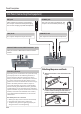
Panel Descriptions Side Panel (Connecting Your Equipment) MIC jack PHONES jack Here is where you connect a microphone. This accepts a miniature stereo phone plug. You can also use plug-in-power microphones. This is for connecting headphones. This accepts a miniature stereo phone plug. [MIC] knob [PHONES] knob This adjusts microphone input sensitivity. This adjusts the volume level for headphones. MIDI OUT/THRU connector, MIDI IN connector p.
Basic Operation Turning the Power On and Off Once everything is properly connected (p. 8–10), be sure to follow the procedure below to turn on their power. If you turn on equipment in the wrong order, you risk causing malfunction or equipment failure. Turning Off the Power Automatically (Auto Off) * Before turning the unit on/off, always be sure to turn the volume down. Even with the volume turned down, you might hear some sound when switching the unit on/off.
Basic Operation Using the Menus This explains how to display menus and make settings for video and audio, and for the V-1HD itself. * The menu is shown on the monitor connected to the PREVIEW connector (p. 9). * Video-switching operations cannot be performed while a menu is displayed. Displaying/exiting menus The V-1HD has three types of menus (SETUP, MEMORY, and AUDIO).
Basic Operation Saving/Recalling Settings (Memory) You can take the current settings, including video and audio settings and the state of the operation panel, and save them as a single set in the V-1HD’s internal memory, for later recall and use when needed. The V-1HD is provided with eight memories. Settings saved in memory What you can save in memory are the MEMORY menu and AUDIO menu settings and the state of the operation panel. Each uses a different method for saving its values in memory.
Video Input/Output Settings Setting the Video Input/Output Format You set the input/output format to match the incoming video signal. * Before setting the input/output format, first be sure to turn off the power to the V-1HD. 1. Slide the [FORMAT] switch on the rear panel to set the input/output format. Adjusting Output Video You can adjust the main output video or preview output video to match the equipment receiving output from the V-1HD.
Video Input/Output Settings Switching the View Mode of Preview Output Inputting Copyright-protected (HDCP) Video Three types of view modes are available for the V-1HD’s preview output. To input copyright-protected (HDCP) video from a Blu-ray Disc player or the like, you make the setting for enabling HDCP input. 1. Press and hold the [(TAP) BPM] button (for 2 * The V-1HD must be connected to an HDCP compatible display for HDCP protected video to be connected.
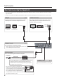
Video Operations Switching the Video You can switch the video input to bus A and to bus B of the video mixer. Switching Using the A/B Fader You operate the A/B fader to switch between two video feeds. The video on the bus toward which the A/B fader is flipped is output (A/B mode). 1. Use the [A-1] through [A-4] and [B-1] through [B-4] buttons to select the video to input on bus A and bus B. 3. Move the A/B fader to the bus A position or the bus B position.
Video Operations Switching Using the TRANSFORMER Buttons You can switch video using the TRANSFORMER buttons, without using the A/B fader. This section describes the operations, using the factory-default memory number 1 settings as an example. 1. Use the [A-1] through [A-4] and [B-1] through [B-4] buttons to select the video to input on bus A and bus B. Changing the operation of the TRANSFORMER buttons Bus A 1. Press the [MEMORY] button to display the Bus B 2. Use the [ MEMORY menu.
Video Operations Switching in Time with Music (BPM Sync) You can switch video in time with a musical beat. The video is switched automatically, with no operation of the A/B fader or the TRANSFORMER buttons. Setting BPM using a numerical value Setting BPM using a numerical value makes the video switch beat by beat. 1. Use the [A-1] through [A-4] and [B-1] through [B-4] buttons to select the video to input on bus A and bus B.
Video Operations Switching Automatically (Auto Scan) Using a Different Transition Pattern The video on channels 1 through 4 is switched automatically in sequence. A variety of transition patterns are available for mix and wipe transition effects. To use a different pattern, change the transition pattern assigned to the [MIX] or [WIPE] button. MEMO 55 Any channels carrying no video input are skipped. 55 Switching the video manually is not possible while an automatic switch is in progress. 1.
Video Operations Applying a Fade to the Main Output Video (Output Fade) You can apply a fade to the V-1HD’s main output video. This lets you make the main output video fade to a black (or white) picture at times when you want to suppress video output, such as during intervals in a presentation, event or band performance. Applying a fade-out 1. Turn the [OUTPUT FADE] knob all the way clockwise or counterclockwise. Freezing Input Video (Freeze) This temporarily pauses the incoming video.
Video Effect Operations You can apply effects to the main output video. The V-1HD has nine types of built-in filter effects and ten types of built-in compositing effects. Using Filter Effects These apply effects such as changes in video color tone and appearance to the entire video. You can set filter effects separately for the video on bus A and on bus B. Selecting a Filter Effect Applying Filter Effects 1. Press the [MEMORY] button to display the 1. Output the video to which you want to apply 2.
Video Effect Operations Using Compositing Effects These composite the bus A video and the bus B video. * When compositing effects are turned on for either bus A or bus B, no effects can be applied to the other bus. Selecting a Compositing Effect Compositing Using Luminance Key 1. Press the [MEMORY] button to display the This composites video with white or black areas made transparent onto a background video. Using luminance keying lets you superimpose logos or text onto a background picture.
Video Effect Operations Compositing Using Chroma Key Compositing Using Split This composites video shot against a blue or green background against a different background video. This composites two video streams in a split screen. The bus A video is displayed above or on the left, and the bus B video is displayed below or on the right. Blue or green NOTE 55 Chroma-key composition sometimes leaves color or small artifacts at the edges of the extracted video, but this is not a malfunction.
Video Effect Operations Compositing Using Picture-in-Picture This composites video in an inset screen onto a different background video. Inset screen Background video 1. Follow the procedure in “Selecting a Compositing Effect” (p. 22) to select “PinP 1/4,” “PinP 1/3,”or “PinP 1/2.” 2. Press the EFFECTS A (or B) [ON] button to turn on the effect (lighted). 3.
Audio Operations Adjusting the Volume Level This adjusts the volume level of input audio and output audio. 1. Press the [AUDIO] button to display the AUDIO menu. 2. Use the [ ] and [ ] buttons to select the input audio whose volume level you want to adjust. MEMO 55 When the [AUDIO] button is illuminated, the [A-1] through [A-4] and [B-1] through [B-3] buttons function as shortcuts for AUDIO menu selection. You can select audio whose volume level you want to adjust by pressing a shortcut button.
Audio Operations Applying Effects to Audio You can apply effects to audio that is input and output to adjust its tone quality. Applying Effects to Input Audio Delay (DELAY) This applies effects and adjusts tone quality for audio input via AUDIO IN, MIC, and HDMI IN. The following table shows the effects you can use with the different input audio streams. Input audio Effects EQ DELAY GATE COMP HPF ( ( — — — ( ( — — — AUDIO IN ( MIC HDMI IN ( ( ( ( 1.
Audio Operations Applying Effects to Output Audio This applies effects and adjusts the sound quality for output audio. 1. Press the [AUDIO] button to display the AUDIO menu. 2. Use the [ ] and [ ] buttons to select the effect menu item you want to use. * For more information about effects, refer to the following section. 3. Use the A/B fader to adjust the setting value. 4. Press the [AUDIO] button to quit the menu. Equalizer (EQ) Adjusts the tone quality for each frequency band.
Audio Operations Interlinking Audio Output to Video Switching (Audio Follow) You can associate audio with a video switch so that when the video is switched, only the HDMI audio of the output video is output, and other HDMI audio is automatically muted. You can also use Audio Follow with audio input via AUDIO IN or MIC. 1. Follow the procedure in “Adjusting the Volume Level” (p. 25) to adjust the volume to the level you want to output. 2. Press the [AUDIO] button to display the AUDIO menu. 3.
Other Features Returning to the Factory Settings (Factory Reset) Operating the V-1HD by Remote Control You can return the values of settings on the V-1HD to their factory defaults. If operation that differs from what is described in the Owner’s Manual occurs even when the steps described are followed correctly, try performing a factory reset. You can use V-1HD RCS or V-1HD Remote dedicated software to remotely control the following functions on the V-1HD from a computer or tablet connected via USB.
Appendices Menu List * The menu is shown on the monitor connected to the PREVIEW connector (p. 9). MEMORY Menu ([MEMORY] button g [A-1]–[A-4] and [B-1]–[B-4] buttons) Menu item Value MEMORY1–MEMORY8 NEGATIVE, EMBOSS, COLORIZE, COLORPASS, POSTERIZE, SILHOUETTE, MONOCOLOR, FINDEDGE, FLIP, WHT-L.KEY (*1), BLK-L.KEY (*1), EFFECTS A GRN-C.KEY (*1), BLU-C.
Appendices MEMORY 1–8 factory-default values Menu item EFFECTS A EFFECTS B WIPE MEMORY 1 COLORPASS FLIP V-RIGHT/s MEMORY 2 NEGATIVE COLORIZE BLOCK/s MEMORY 3 PinP 1/2 PinP 1/2 H-UP MEMORY 4 PinP 1/4 PinP 1/4 V-RIGHT MIX MIX MIX FAM FAM TRANSFORMER A TRANSFORM TRANSFORMER B TRANSFORM TRANSFORM TIME 1.0sec 2.0sec 1.0sec 1.
Appendices AUDIO Menu ([AUDIO] button) Menu item Value (bold text: default value) Explanation HDMI IN 1 : HDMI IN 4 LEVEL AUDIO IN MIC 0–100–127 Adjusts the volume level of the respective input audio streams. * 100 = 0.0 dB, 127 = +6.0 dB MASTER OUT LEVEL 0–100–127 AUDIO FOLLOW EQ Hi ON, OFF -15–0–15dB MEMORY1–MEMORY8 EQ Hi FREQ 700Hz–8.00KHz–11.0KHz EQ Mid -15–0–15dB HDMI IN 1 : EQ Mid FREQ 20.0Hz–2.50KHz–10.0KHz HDMI IN 4 AUDIO IN EQ Mid Q 0.5–16.
Appendices Menu item Value (bold text: default value) REVERB LEVEL 0–127 REVERB TIME 0.0–1.0–5.0sec Specifies the type of reverb. ROOM REVERB TYPE HALL MASTERING ON, OFF MASTERING NS 0–127 MASTERING ENHANCER 0–127 MASTERING Hi 0–127 MASTERING Mid 0–127 MASTERING Lo 0–127 A. FOLLOW AUDIO IN 1–4, OFF A. FOLLOW MIC 1–4, OFF SETUP Menu Explanation Adjusts the return level from reverb of the audio. A setting of “0” results in no reverb applied. Adjusts the length of the reverb.
Appendices Menu item AUTO SCAN TIME CH1 : AUTO SCAN TIME CH4 AUTO SCAN TRANS TIME AUTO SCAN SEQUENCE DEINTERLACE MODE A/B MODE FREEZE MODE Value (bold text: default value) Explanation OFF, 1–5–120sec When the Auto Scan function is on, specifies the video display interval. If this is “OFF,” video switching does not affect. When the Auto Scan function is on, this sets the length of time for applying a video transition. NORMAL, RANDOM Specifies the order in which video signals are shown.
Appendices Menu item Value (bold text: default value) Explanation WIPE SW ON, OFF [WIPE] button MIX SW ON, OFF [MIX] button CUT SW ON, OFF [CUT] button FREEZE SW ON, OFF [FREEZE] button MEMORY SW ON, OFF [MEMORY] button AUDIO SW ON, OFF [AUDIO] button EFFECTS SW ON, OFF EFFECTS A and EFFECTS B [ON] buttons EFFECTS VOL ON, OFF [EFFECTS A] and [EFFECTS B] knobs OUTPUT FADE VOL ON, OFF [OUTPUT FADE] knob A/B FADER ON, OFF A/B fader Specifies the background color of channels that
Appendices Troubleshooting If you suspect a malfunction, please check the following points. If this does not resolve the problem, contact a nearby Roland Service Center. Problem Items to check Action Page Video-related problems No picture is input. Are the [A-1] through [A-4] and [B-1] Video whose format differs from the [FORMAT] switch through [B-4] buttons flashing in setting is input. Input video that is compatible with white? the specified format.
Appendices Transition Effects List MIX Effect MIX FAM NAM MOSAIC Explanation As the original picture gradually disappears, the next video is overlaid and progressively grows more visible. Video transitions are made with the luminance levels of the two video streams maintained unchanged. * This is an abbreviation of “full additive mix.” The two video streams are compared, and transitions are made with display during transition starting with levels of high luminance.
Appendices Block Diagram Video Block HDMI INPUT 1 HDMI INPUT 2 EDID I/P CONV FS FREEZE EDID I/P CONV FS FREEZE EDID I/P CONV FS FREEZE EDID I/P CONV FS FREEZE HDMI INPUT 3 HDMI INPUT 4 FORMAT 5 1080p 5 1080i 5 720p MULTIVIEWER 1 3 2 4 Audio Block MIC GAIN HPF EQ LEVEL GATE COMP DELAY FOLLOW +3.
Appendices 1 FORMAT 5 1080p 5 1080i 5 720p 2 INPUT SELECT 3 A-BUS EFFECTS A B-BUS EFFECTS B TRANSITION 5 CUT 5 MIX 5 WIPE PGM P/I CONV OUTPUT FADE PST HDMI OUTPUT 4 PGM PST MULTI-VIEW MENU OSD P/I CONV HDMI PREVIEW L R REVERB HDMI OUTPUT HDMI PREVIEW MASTER LEVEL EQ AUDIO OUT MASTERING PHONES REVERB LEVEL PHONES LEVEL REVERB 39
Appendices Main Specifications Roland V-1HD: HD Video Switcher 9 Video Video Processing Input Connectors Output Connectors Input Formats Output Formats 4:2:2 (Y/Pb/Pr), 8-bit Type A (19 pins) x 4 HDMI INPUT 1–4 * HDCP Supported Type A (19 pins) HDMI OUTPUT * HDCP Supported Type A (19 pins) HDMI PREVIEW * HDCP Supported 720/59.94p, 720/50p (FORMAT switch = 720p) 1080/59.94i, 1080/50i (FORMAT switch = 1080i or 1080p) 1080/59.
Appendices 9 Others Power Supply Current Draw Power Consumption Operation Temperature Dimensions Weight Accessories AC Adaptor 1.5 A 18 W +0 to +40 degrees Celsius +32 to +104 degrees Fahrenheit 313 (W) x 102 (D) x 59 (H) mm 1.2 kg (excluding AC adaptor) 2 lbs 10-2/5 oz Owner’s Manual, AC adaptor, Power cord, Cord hook * 0 dBu=0.775 Vrms * This document explains the specifications of the product at the time that the document was issued. For the latest information, refer to the Roland website.
For the U.K. IMPORTANT: THE WIRES IN THIS MAINS LEAD ARE COLOURED IN ACCORDANCE WITH THE FOLLOWING CODE. NEUTRAL BLUE: BROWN: LIVE As the colours of the wires in the mains lead of this apparatus may not correspond with the coloured markings identifying the terminals in your plug, proceed as follows: The wire which is coloured BLUE must be connected to the terminal which is marked with the letter N or coloured BLACK.
For EU Countries For China 43
Roland Service Centers and Distributors When you need repair service, access this URL and find your nearest Roland Service Center or authorized Roland distributor in your country. http://roland.cm/proav_service Roland Service Centers and Distributors When you need repair service, access this URL and find your nearest Roland Service Center or authorized Roland distributor in your country. http://roland.