To resize thickness, move all items on the front cover to left or right on the master page. VM-C7200/VM-C7100 QUICK START QUICK START Thank you, and congratulations on your choice of the Roland VM-C7200 (VM-C7100) V-Mixing Console. The documentation for the VM-7000 Series consists of the volumes as listed below.
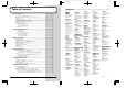
To resize thickness, move all items on the front cover to left or right on the master page. Table of Contents Getting Started ........................................................................................4 How to Use The QUICK START...............................................................................................................4 Installing the VM-C7100/C7200 Digital Mixing System.......................................................................5 Connections.....................
Table of Contents Some Special Features.........................................................................72 The Spectrum Analyzer ........................................................................................................................... 72 5.1 Surround .............................................................................................................................................. 73 Speaker Modeling........................................................................
Getting Started How to Use The QUICK START The QUICK START basically explains the operations as follows: Mixing Operations Important notifications to prevent considerable damage to your equipment. Now let’s do some mixing. This chapter describes two-channel – stereo – mixing of connected sources that will be sent out from the system through its MAIN OUT jacks. Setting the Input Gain Let’s adjust the input gain levels of all of your connected instruments and so on.
Getting Started Installing the VM-C7100/C7200 Digital Mixing System The VM-C7100/C7200 Digital Mixing System consists of two units – the mixing console and the mixing processor. About the VM-C7100/C7200 Digital Mixing System The Mixing Console fig.001 All mixing activities take place on the mixing console, including the adjusting of faders, the assignment of signals to busses and the application of effects. Place the console in an area such as a control room.
Getting Started To Connect the VM-C7100/C7200 Digital Mixing System Use a pair of AES/EBU digital audio cables to connect the mixing console and mixing processor. These cables are supplied as a set with the mixing console. fig.003 Use the supplied pair of AES/EBU Digital Audio Cables.
Getting Started Connections To avoid problems and/or damage to speakers or other devices, always turn down the volume and turn off the power on all devices before making any connections. Basic Connections Rear Panel of the Mixing Console fig.004 Microphone, Sub Mixer, MD/CD Player Monitor in the Control Room Speaker Amp Mixing Processor Digital Powered Speaker (Roland DS-90 etc.
Getting Started Front Panel of the Mixing Processor fig.005 Channel Insert (Effects Processor) Monitor Speaker Synthesizer, Sound Module, etc Branch Cable (e.g.
Getting Started Rear Panel of the Mixing Processor fig.006 Digital Multi-track Tape Recorder (TASCAM/ADAT) 8 ch To R-BUS Compatible Device Roland DIF-AT (Interface Box) R-BUS Cable AC Power Supply VM-24E (Option) VM-24C (Option) Main Output Word Clock Connector on Digital Recorder or similar device MB-24 (Option) Cable supplied with the VM-24C Digital Input/Output DAT/MD Recorder, etc.
Getting Started Turning On the Power After you have finished making connections (QUICK START: p.7), be sure to turn on all of your devices in the proper order, as described in the instructions below. Powering up in the wrong order may cause malfunctions and/or damage to speakers and the devices. Always make sure that each device’s volume level is turned down before turning on its power.
Getting Started 4 Set [POWER] to ON on the front panel of the mixing processor. The CTRL indicator blinks during startup. When startup is completed, the indicator lights in green. 5 6 After the CTRL indicator on the processor has turned green, set [POWER] to ON on the rear panel of the mixing console. When connected in cascade (Owner’s Manual “Settings related to cascade conection” p.41), turn on the power of the Slave processor (“2nd UNIT”) first.
Getting Started To Adjust the Brightness of the Display You may wish to adjust the brightness of the display immediately after power-up, under unusual viewing conditions, or after the unit has been on for an extended period of time. Adjust the brightness of the screen using the [CONTRAST] knob on the left bottom of the display. fig.
Getting Started Restoring the Original Factory Settings You can restore the system’s parameters to their original default settings using the following procedure. • The Factory Reset function deletes all of your own settings. • Be sure to turn off the power of all amplifiers and speakers before executing Factory Reset. fig.103 1,2 3 2 4 1 2 3 Turn off the power of the mixing console. Hold down [PROJECT] and [F1] while turning on the console’s power.
Getting Started Setting the Internal Clock The mixing console unit contains an internal clock. When you store a Project, the current time, day, and month information is automatically stamped into the Project (Time Stamp). This makes the management of Projects easier, since you can sort them in day/time order. When you turn on the power for the first time after purchase, be sure to set your system’s date and time by following the instructions below. fig.
Getting Started 3 Press [F5](DATE). The “SYS DATE” display appears. fig.202 4 5 6 Press CURSOR [DOWN] to move the cursor to the “ADJUST DATE / ADJUST TIME” field. Set the current date. Turn [V1](YEAR), [V2](MONTH), [V3](DATE) to select the current date, and then press [F1](SET) to confirm your selection. Set the current time. Turn [V4](HOUR), [V5](MIN), [V6](SEC) to select the current time, and then press [F4](SET) to confirm. The time you set becomes effective immediately. The date and time are set.
Getting Started Preparing a Memory Card You can store your current mixing settings on your console as a Project onto a memory card (SmartMedia). A Project is a group of parameter settings that the system memorizes. Such settings include Scenes (Owner’s Manual: p.244) and Automix data (Owner’s Manual: p.232). You can instantly store/ recover these settings at any time by overwriting/reloading the Project.
Getting Started 1 Insert the memory card into the mixing console. Insert the memory card with the golden terminal strip upside. fig.009 2 Hold down [SHIFT] and press [PROJECT]. 3 Press CURSOR [DOWN] to move the cursor to the lower field. 4 Press [F6](MEMORY CARD). The “SYS M.CARD” display with the card information appears. fig.203 5 Press [F2](FORMAT). The “CONFIRM / Format Card, OK?” message appears on the display.
Getting Started 6 Press [F5](OK). To cancel, press [F6](CANCEL). 7 When the “CONFIRM / Really Sure?” message appears, press [F5](OK) again. To cancel, press [F6](CANCEL). After the formatting is finished, the “MESSAGE / Completed” message appears on the display. 8 Press [F6](EXIT). • To return to the original display (the “LEVEL METER” display), press [LEVEL METER].
Getting Started To Create a New Project fig.10 6 Owner’s Manual “Storing and Recalling All Mixer Setings (Project)” p.50 1 3,4 5 7 2 1 Press [PROJECT]. The “PROJECT” display appears. 2 Press CURSOR [DOWN] to move the cursor to the lower field. 3 Press [F2](NEW). The “CREATE NEW PROJECT” message appears on the display. 4 Press [F2](CREATE). The “CONFIRM / Create New Project, OK ?” message appears.
Getting Started Turning Off the Power Points to check before turning the power off • Have you stored your Automix data on a memory card? Your current Automix data is stored in the console’s temporary memory – this memory is cleared when you turn off the power. Be sure to save any Automix data you wish to preserve onto a card before powering down.
Getting Started 4 5 6 7 Set [POWER] to OFF on the front panel of the mixing processor. Turn off the power of connected analog devices (instruments, sound modules, effects processors, microphones, CD players, MD players, tape recorders, etc.). Turn off the power of connected digital devices (DAT, MD recorder, hard disc recorder, etc.). Turn off the power of any connected digital multi-track tape recorder.
Before Mixing Operations Internal Signal Flow The diagram below provides an overview of the audio signal flow. For details, refer to the “Block Diagram” attached to the processor (VM-7200/ 7100). fig.104 R-BUS MULTI IN 1–24 MULTI OUT 1–24 INPUT 1–24 FLEX BUS MASTER 1–12 B U S 1 MAIN OUT L/R CUE OUT L/R 2 1. Input Channels There are two input modes to this system – [INPUT] and [MULTI IN]. INPUT...
Before Mixing Operations 2. Busses / Output Routes MULTI OUT A multiple output channel to which signals from any input channel and/or Flex Bus can be routed. Digital multi-track output to a digital multi-track recorder can be performed by installing an optional VM-24E (sold separately) in the system. You can also send analog track outputs from ASSIGNABLE OUT jacks.
Before Mixing Operations How to Operate This System When operating this system, you’ll most frequently use the cursor, the knobs [V1]-[V6], and buttons [F1]-[F6] beneath the display. This chapter explains the display, and how these knobs and buttons interact with the display. fig.104 Display Buttons F1-F6 Cursor buttons Knobs V1-V6 Faders INPUT/MULTI IN buttons The Display (example) fig.
Before Mixing Operations To Change Parameters To change the value of a parameter, move the cursor to select a parameter, and use the knobs [V1]-[V6], faders, and/or buttons [F1]-[F6] to change its value, as described below. To Move the Cursor The cursor – a bold rectangle on the display – selects a single parameter or group of parameters so that their values can be adjusted. To move the cursor, press CURSOR [UP] [DOWN] [LEFT] [RIGHT].
Mixing Operations Now let’s do some mixing. This chapter describes two-channel – stereo – mixing of connected sources that will be sent out from the system through its MAIN OUT jacks. Setting the Input Gain Let’s adjust the input gain levels of all of your connected instruments and so on. (If you are working on digital connected sources, you do not have to read this section.) fig.107 Owner’s Manual “Gain, Phantom Power Supply, Phase and Attenuator” (p.
Mixing Operations 2 Use the fader of each channel you wish to adjust to set the input gain level of its connected microphone/instrument/ audio device. (+4 to -64dB) Do this by first turning up each instrument’s own output volume as much as possible so that it produces a strong, loud signal. Next, on the console, turn its channel’s input gain level as high as possible within the displayed level-meter range. If the input gain goes beyond OVER, appears on the level-meter.
Mixing Operations Setting the Channel Levels and L/R Pans Here you can set the output level and L/R pan of each channel in the Main out mix or the Cue bus. You can see each level and pan setting shown numerically on the display. fig.108 3,5 3,5 1 28 4,5 2,3 SHIFT 1 Press [INPUT] or [MULTI IN] to select the type of channel you wish to set up. Owner’s Manual “Setting up ON/OFF, SEND LEVEL and PAN for a Channel” (p.
Mixing Operations 2 Press [CH LEVEL]. [CH LEVEL] lights in red and the “CH LEV/PAN” display appears. fig.208 3 Use the fader of the channel you wish to adjust to change its output level. To set the channel level at 0db (100), hold down [CH LEVEL] and press [CH EDIT] of the channel you wish to set at 0db. 4 Press [CH PAN] [CH PAN] lights in red and the “CH LEV/PAN” display appears. 5 Use the fader of the channel you wish to adjust to change its stereo position.
Mixing Operations Setting the Master Level and Master Stereo Balance Let’s now set the total output level and stereo balance for the Main out mix containing all Input and Multi In sources. fig.109 3 2,4 1 1 2 3 30 Press [CH LEVEL] to light [CH LEVEL] in red. Use the [MASTER] fader to set the master level for the Main out. Press [CH PAN] to light [CH PAN] in red. Owner’s Manual “Setting Master Mix Levels and Stereo Balance” (p.
Mixing Operations 4 Use the [MASTER] fader to set the overall stereo balance of the Main out. Move the fader upwards for right(R) pan, downwards for left(L) pan.
Mixing Operations Adjusting a Signal’s Tone (Equalizer) You can set the desired tone quality of each signal by using an equalizer (EQ). In this system, each channel provides a parametric EQ. You can select from a 4-band- or a 3-band-plus-1-effect-type EQ. The high-range and low-range bands are shelving type EQs. The middle-high-range and middle-low-range bands are peaking type EQs. fig.110 2 3 2 1 2 5 4 1 Press [INPUT] or [MULTI IN] to select the type of channel you wish to set up.
Mixing Operations fig.209 3 Press [F1](EQ ON) to turn on the equalizer. “EQ ON” highlights in black. 4 To turn off the equalizer, press [F1] again. “EQ ON” returns to normal. Press CURSOR [UP] [DOWN] to select the desired band. HI (high-range), HI-MID (mid-high-range), LO-MID (middle-low-range), LO (low-range). 5 Adjust the settings for the selected band. GAIN Turn [V2](GAIN) to add (“boost”) or reduce (“cut”) gain (-15.0 to +15.0dB). FREQUENCY Turn [V3](FREQ) to adjust the center frequency.
Mixing Operations Setting Up a Monitor You can monitor the system through headphones connected to the PHONES jack, or through monitoring speakers connected to the MONITOR OUT jack. You will hear the same sound from both outputs. You can monitor the Cue bus, the Main out, or any Flex Bus by itself. fig.113 2 4 1 13 Press [SOURCE SELECT]. The “MONITOR SOURCE” sub-window appears on the display. fig.211 34 Owner’s Manual “Mixing Procedure 2 (Output and Monitor)” (p.
Mixing Operations 2 Turn [V1](SELECT) to select the output you want to monitor. 3 Turn [DIGITAL(MASTER)] to adjust the monitor out level. • If you have a device connected to the LINE OUT jack on the console, turn [LINE OUT LEVEL] to set the favorable line out level in advance. • If you are using headphones, turn [PHONES LEVEL] to adjust the volume. 4 Press [F6](EXIT) to exit.
Mixing Operations Coupling Adjacent Channels If you are editing a stereo source, you can couple adjacent odd- and evennumbered channels – changes you make to either channel will affect both. fig.112 5 2 1 Press [FADER UTILITY]. The “FADER UTIL” display appears. 2 Press [F1](CHANNEL LINK). fig.210 36 3 4 1 Owner’s Manual “Simultaneously Controlling the Signals of Multiple Channels (Link and Group)” (p.
Mixing Operations 3 Press [PAGE UP] [PAGE DOWN] to display the type of channels you want to link. Select from “INPUT”, “MULTI IN”, or “FLEX BUS”. 4 5 Press CURSOR [UP] [DOWN] to select the group of six channels containing the channels you want to link. Press [F1]-[F6] to turn ON (black highlight) the Channel Link of any pair you wish to couple. To cancel Channel Link, press [F1]-[F6] again. The following parameters cannot be linked.
Mixing Operations Muting a Channel You can mute a channel’s signal by using the [CH STATUS] buttons. fig.111 Owner’s Manual “Muting a channel (MUTE)” (p.77) 3 1 2 Press [INPUT] or [MULTI IN] to select the type of channel you wish to mute. 2 Press [MUTE] to light [MUTE]. 3 Press [STATUS] of the channel you wish to mute. The muted channel’s [STATUS] button lights in red.
Mixing Operations Storing a Project The current state of the console settings can be stored at any time by updating the Project created on a memory card in the beginning of the session. Let’s store the system’s current state as a Project. fig.114 Owner’s Manual “Storing and Recalling All Mixer Settings (Project)” (p.50) 2 1 1 Hold down [SHIFT] and press [STORE]. The “CONFIRM / Store Current Project OK?” message appears. 2 Press [F5](OK), and then press [F6](EXIT) after storing is completed.
Using Sub Outputs Signals can be sent from the system’s MAIN OUT to a mixdown recorder or a stage speaker system. They can also be sent to other destinations, such as studio monitors, or even to individual tracks of a multi-track recorder. Setting Up Monitor Sends for Studio or Stage The system’s ASSIGNABLE OUTs (Owner’s Manual “Routing Signals to MULTI OUTs and ASSIGNABLE OUT Jacks” p.93) 1-4 can send signals to monitors for a performer in another room –perhaps a studio – or on a stage.
Using Sub Outputs 1 Press [SOURCE/STUDIO2]. The “STUDIO1/2” display appears. fig.212 2 3 Press [PAGE UP] [PAGE DOWN] to go to the “STUDIO 1” or “STUDIO 2” page. Turn [V1](SOURCE SELECT) to select the type of source signal you wish to monitor. The following can be selected. • Input channel 1-24 • Flex Bus 1-12 • Cue bus L/R • Monitor L/R • Main out L/R 4 Turn [V2](LEVEL) to adjust the send level.
Using Sub Outputs To Talk to Someone on a Stage or out in a Studio (Talkback) Owner’s Manual “Talkback and Slate to Player” (p.100) The Talkback feature allows you to talk to a performer or assistant on a stage or in a studio by speaking into the Talkback microphone built into the console. This microphone can be routed to a monitor speaker or other monitoring device. fig.116 MIC 1,2 1 1 Set [INPUT SELECT] to MIC 1. Before switching the [INPUT SELECT], turn [MIC LEVEL] to turn the mic level to 0.
Using Sub Outputs Flex Bus Each mixing processor provides 12 unique multi-purpose busses– these are called “Flex Busses.” A bus – be it a Flex Bus or traditional recording, mixing or Aux bus – is a pathway down which multiple signals can be sent to a common destination. The signals assigned to a Flex Bus can be sent out of the system through various outputs, or can even be directed into another Flex Bus within the system.
Using Sub Outputs Flex Bus Output (MULTI OUT/ASSIGNABLE OUT) Each of the Flex Bus signal can be routed to a MULTI OUT/ASSIGNABLE OUT. You can send its signal to multi-track recorders, external signal processors, or to stage monitors, for example. The MULTI OUTs are primarily used for 24 channel digital recording outputs – which calls for an additional purchased VM-24E – but can also be routed to ASSIGNABLE OUT jacks for analog output. fig.117 3 5 2 1 3 4 61 Press [FLEX BUS MASTER 1-12].
Using Sub Outputs fig.213 3 Press CURSOR [UP] [DOWN] to select the middle field. Turn [V2](BUS MODE) to select “EXT”, and then press [F2](SET) to confirm your choice. (Flex Busses 9-12 do not call for this step.) The Flex Bus is now set to External. 4 5 Press CURSOR [UP] to move the cursor to the upper field. If an effect has been inserted on a Flex Bus, it may lose its effect when you switch from “INT” to “EXT”. When this happens, set the effect’s parameters again (QUICK START: p.54).
Using Sub Outputs Flex Bus Output (Internal) Flex Bus signals can also be routed into the Main out mix. This is convenient if you are planning to add internal effects to signals used in the main mix. fig.118 5 3 2 1 Press [FLEX BUS MASTER 1-12]. If you wish to edit Flex Busses 9-12, proceed to Step 4. 46 34 1 Owner’s Manual “Sending Flex Bus signals to internal destinations” (p.
Using Sub Outputs 2 Hold down [CH EDIT] on the channel strip numerically corresponding to the Flex Bus you wish to edit, and press [MAIN/CUE]. The “MAIN/CUE” editing page on the “CH EDIT” display appears. fig.213 3 Press CURSOR [UP] [DOWN] to select the middle field. Turn [V2](BUS MODE) to select “INT”, and then press [F2](SET) to confirm your choice. The Flex Bus signals are now set to Internal. 4 Press CURSOR [DOWN] to move the cursor to the lower field.
Using Sub Outputs Sending Signals to a Flex Bus Now let’s assign some signals to a Flex Bus. You may wish to monitor a Flex Bus directly – this is possible only when the Flex Bus is set to External (QUICK START: p.44). To monitor the Flex Bus’ signals, select “FBUS 1-12” at “Setting Up a Monitor” (QUICK START: p.34). fig.119 21 3 1 48 462 Press [INPUT] or [MULTI IN] to select the type of channel signals you wish to send to a Flex Bus.
Using Sub Outputs 2 Press FLEX BUS [1]-[6] (lights in red) – or hold down [SHIFT] to select [7]-[12] (lights in green) – to select the Flex Bus to which you want to send the signals. The “FBUS SEND” display appears. fig.214 3 Use the channel faders to adjust each channel’s send level to the Flex Bus. 4 Use the [MASTER] fader to adjust the Flex Bus’ overall level. 5 Repeat Steps 1-4 to assign signals to other Flex Busses. 6 Press [CH LEVEL].
Using On-Board Effects In this system, there are two internal effects available to the Input and Multi In channels, and an additional effect provided for the Main out and monitors. In addition, you can install optional VS8F-2 Effects Expansion Boards – sold separately – allowing the system to produce up to nine effects simultaneously from a single mixing processor (see list below).
Using On-Board Effects Send-Return Loop Effect Let’s try creating a send-return loop effect using the internal effects 1-8. fig.120 7 6 3 1 Owner’s Manual “Determining the effect position” (p.110) 2,5 4 1 Press [EFFECTS 1-8]. The “EFFECTS MENU” display appears. fig.
Using On-Board Effects 2 Press CURSOR [UP] [DOWN] to select the FX field. FX-1-3 are located in the upper field, FX-4-6 in the middle, and FX-7-8 in the lower. If you have not installed an optional VS8F-2, you can only select FX1 or FX-2. 3 Press [F2], [F4], or [F6] to “EDIT” the effect. The “EFFECT (1-8)” editing display appears. 4 Press [PAGE DOWN] to go to the “ASSIGN” page. At this point, you set the insertion point of the effect. fig.216 Flex Bus channel to which an effect is inserted.
Using On-Board Effects 8 Set the Flex Bus’ output destination to the Main out. 1. Press [FLEX BUS MASTER 1-12]. 2. Hold down [CH EDIT] numerically corresponding to the Flex Bus to which you have inserted the effect, and press [MAIN/CUE]. Go to QUICK START : p.43 for Flex Bus setup instructions. 3. Press CURSOR [UP] [DOWN] to select the middle field. Then turn [V2](BUS MODE) to select “INT”, and then press [F2](SET) to confirm.
Using On-Board Effects Setting the Onboard Effect Position and Value You can insert an internal effect at any of several points along a signal’s path. Most effects are inserted on a Flex Bus or the Main out, but there are some effect types you may wish to insert directly into an Input or Multi In channel. First, make a decision as to where you wish to insert an effect. Then adjust the appropriate send/return values. fig.
Using On-Board Effects 2 Press CURSOR [UP] [DOWN] to select the FX field. FX-1-3 are located in the upper field, FX-4-6 in the middle, and FX-7-8 in the lower (“MST FX MENU” does not call for this step). If you do not have an optional VS8F-2 installed, you can only select FX-1 or FX-2. 3 Press [F2], [F4], [F6], or [F2] on “MST FX MENU” to “EDIT”. The “EFFECT (1-8)” or “MASTER FX” display appears. 4 Press [PAGE DOWN] to go to the “ASSIGN” page. At this point, you set the insertion point of the effect.
Using On-Board Effects 7 Turn [V2](POSITION) to define the insertion point of the effect. The insertion points are as listed below. (Turn [V1] for “MASTER FX” to select from the following: OFF, MAIN, MONITOR.
Using On-Board Effects 8 If you have inserted the effects on an Input or Multi In channel or a Flex Bus, turn [V1](CHANNEL SELECT) to select the intended channel/bus, and press [F1](SET). Effects can be inserted on Flex Busses 1-8. The insertion point and the send/return values have been set.
Using On-Board Effects Selecting the Effects A selection of 200 Preset Libraries (P000 to P199) are provided for the effects. You can select a Library that suits your purpose, and copy it to an effect from 1 through 8, or the Master effect. fig.121 4 45 3 1 2 1 Press [EFFECTS 1-8] to select “FX-1-8”, or [SP MODELING (MASTER FX)] for “MASTER FX”. The “EFFECTS MENU” or “MST FX MENU” display appears. 2 Press CURSOR [UP] [DOWN] to select the FX field.
Using On-Board Effects 3 Press [F1], [F3], [F5], or [F1] on “MST FX MENU” to call up the “LIBRARY”. The “COPY EFFECTS LIBRARY” sub-window opens on the display. fig.217 4 First, turn [V1](SELECT GROUP) to select “U” (User’s) or “P” (Preset) group. (As preset at the factory, the User’s group holds the same effects as the Preset group.) Next, turn [V2](SELECT NUMBER) to select the desired effect (000 to 199) (Owner’s Manual “Algorithm List” p.119).
Using On-Board Effects Using a Channel’s Feedback Delay (Channel Delay) Each channel input has its own delay effect positioned before the EQ in its signal path. The delay is a monaural in/out, and provides various delay effects, including a feedback echo. fig.122 3578 6 2 1 2 Press [INPUT] or [MULTI IN] to select the type of channel you wish to set up. Hold down [CH EDIT] of the channel you wish to apply the delay effect, and press [DELAY]. The “DELAY” page of the “CH EDIT” display appears.
Using On-Board Effects fig.218 3 Press [F1](DLY ON) to turn on the Channel Delay. “DLY ON” highlights in black. 4 5 6 Press CURSOR [DOWN] to move the cursor to the lower field. Turn [V1](DIRECT) to adjust the dry-out level– the original, un-delayed signal. Turn [V4](DELAY TIME) to adjust the delay time. The DELAY TIME sets both the basic delay (shown as TIME) and the spacing between the repeating feedback delays (shown as DISTANCE). The selected delay time is also shown in samples.
Other Important Features Storing a Mixing State (Scene) A Scene is a complete set of mixer settings that can be stored at any point during work on a Project. A Project can store 100 Scenes (00-99), that can easily be recalled. Items Stored in a Scene A Scene holds the level and pan settings of Input and Multi In channels, the Main out, Cue bus, and Flex Busses. It also stores the settings of all equalizers, delays, and internal patch connections.
Other Important Features 1 Hold down [SHIFT] and press [SCENE]. The “SCENE” display appears. 2 The Scene memory function requires an inserted memory card on which a Project has been created or selected. Turn [V1] to select the Scene number you wish to store. The black highlighted field indicates the selected Scene. 3 Press [F3](REGIST). The current settings are stored as a Scene. You can also use the tenkey buttons to store/recall scenes.
Other Important Features To Recall a Scene fig.124 Owner’s Manual “Storing/ recalling/erasing a scene” (p.47) 2 3 1 Hold down [SHIFT] and press [SCENE]. The “SCENE” display appears.
Other Important Features 2 Turn [V1] to select the Scene number you wish to recall. The black highlighted field indicates the selected Scene. 3 Press [F1](RECALL). The selected Scene is recalled.
Other Important Features Setting Signal Routings on the Display (Virtual Patchbay) You can establish the routing of signals by making connections between input jacks and ASSIGNABLE OUT jacks using virtual cables shown on the display. fig.125 3 1 1 Hold down [SHIFT] and press [EZ ROUTING]. The “EZ ROUTING” display appears. fig.219 66 2 Owner’s Manual “Virtual patchbay” (p.
Other Important Features 2 3 Press CURSOR [UP] [DOWN] [LEFT] [RIGHT] to select a group of six input jacks or output jacks. Turn [V1]-[V6] to change their connections. • For internal connections using the Virtual Patchbay, signals can also be assigned to several destinations. Multiple signals, however, can not be simultaneously assigned to a single destination. Possible IN 1 OUT 1 IN 2 OUT 2 IN 3 OUT 3 IN 4 OUT 4 The MULTI OUT connection thread can be cut off by turning the knob all the way to the left.
Other Important Features Simultaneously Adjusting the Levels of Multiple Channels You can group multiple channels together, allowing you to control all of the channels simultaneously. You can use, for example, a single fader to boost or cut all of the grouped channels’ levels at once. This can be convenient in situations where you want to maintain volume balances between a set of channels while raising or lowering their overall level, such as when working with multiple microphones on a drum kit.
Other Important Features 1 Press [FADER GROUP MASTER 1-24] The “FADER GROUP” display appears – the faders now function as Fader Group Masters. 2 Press [CH EDIT] of the Fader Group you wish to edit. The “CH EDIT” display appears with the Fader Group setting screen. fig.220 3 4 In the lower right “GROUP VIEW” field of the screen, use CURSOR [UP] [DOWN] [LEFT] [RIGHT] to select a set of six channels containing the first channel you wish to include in the group.
Other Important Features To Mute a Group of Multiple Channels (Mute Group) You can also mute a group of multiple channels simultaneously by using the Mute Group function. This system provides nine Mute Groups. By turning a Mute Group on or off, all channels registered in the group are muted or un-muted simultaneously. The following channels can be grouped. • Input channels 1-24 • Multi In channels 1-24 • Flex Bus Masters 1-12 • Fader Group Masters 1-24 fig.
Other Important Features 1 Hold down [SHIFT] and press [MUTE GROUP]. The “MUTE GROUP” display appears. fig.221 2 Press [PAGE UP] [PAGE DOWN] to select the Mute Group you wish to set up. For example, if you wish to set up Mute Goup 2, select “GRP 2”. 3 4 Press CURSOR [UP] [DOWN] [LEFT] [RIGHT] to select the set of six channels that contains the first channel you want to register in the Mute Group. Press [F1]-[F6] to turn ON (black highlight) / OFF (normal) the Mute Group.
Some Special Features This chapter introduces some other special features. The instructions for their use can be found in the Owner’s Manual. The Spectrum Analyzer This system is equipped with a Spectrum Analyzer, with which you can measure the frequency characteristics of signals. This Spectrum Analyzer (referred to as “analyzer” for the remainder of this section) divides input signal frequencies into 31 narrow bands, and displays the momentary level of each band on a graph in real-time.
Some Special Features 5.1 Surround This system supports multi-speaker surround sound. A normal stereo audio system consists of two speakers – left and right in front of the listener – for stereo playback. A surround system creates a threedimensional sound field with three to six speakers located in the front and rear, as well as to the left and right. You can create surround sound by positioning and adjusting the Flex Bus outputs on the “SURROUND” editing display.
Some Special Features Speaker Modeling This system provides a powerful collection of exclusive Roland speaker modeling effects. With Roland’s DS-90 Powered Monitors connected, you can simulate almost any speaker system, ranging from commonly used pro monitor speakers to those found on small TV sets and portable radios. This allows you to try out your mix on a variety of virtual speaker systems.
Using EZ Routing Templates The system provides nine preset EZ Routing templates that can help you quickly configure your console for a wide variety of applications. These templates cover a range of mixing tasks: studio and stage recording, mixing, live sound with stage monitors, and MIDI synchronization for working with bands that play along to MIDI sequencers, for example. They also suggest some of the many ways in which you can configure this highly flexible system.
Using EZ Routing Templates 8 Track MDM With MIDI Sound Module Recording This EZ Routing template configures the system for recording live elements (vocal, guitar, etc.) along with sequenced MIDI backing tracks (synthesizers, rhythm-box, etc.) on an 8 track digital recorder. (VM-C7200/C7100 Libraries “8 TRACK MDM WITH MIDI SOUND MODULE RECORDING” p. 3) See your Owner’s Manual for more details. . INPUT channel Front Panel on the Processor E.Bass Monitor Speaker, Headphone for Players A.
Using EZ Routing Templates 1 Make your connections as shown on the left. • Use MIDI cables to connect the system to your MIDI devices (sound module, sampler, digital multi-track recorder, etc.). • You can set up as many as four monaural monitor outputs for your performers. Connect their headphones or monitor amplifiers to FLEX BUS OUTs 9-12. • Route any guitar or electric bass through direct boxes or a compact effect processor connected to the system input.
Using EZ Routing Templates 5 Set the input gain of each signal on the console. 1. Press [INPUT]. 2. Press [PREAMP GAIN]. 3. Use the faders to adjust the input gain level of each source. Owner’s Manual “Gain, Phantom Power Supply, Phase and Attenuator” (p.68) • If you are using any condenser microphones, activate their PHANTOM power. 6 Adjust each EQ as necessary. 1. Press [CH EDIT] on the desired channel. 2. Press [PAGE UP] [PAGE DOWN] to select the “EQ BAND” page. 3.
Using EZ Routing Templates 9 Adjust the effects. 1. Press [EFFECTS 1-8]. Owner’s Manual “Using the Internal Effects” (p.109) 2. Press CURSOR [UP] [DOWN] to navigate to the field showing the desired effect’s name, and press [F2] [F4] or [F6] to select the effect. • The following are the effects chosen by the “MIDI+8TrREC” template in a system with three optional VS8F-2 Effects Expansion Boards (sold separately) installed.
Using EZ Routing Templates About The Word Clock To share digital audio signals between this system and any external digital device, you must first define the Word Clock Master/Slave to each device. The setting orders depend on the types of devices you are using. When you change settings on a digital connected device, a loud noise may occur. Always turn down the volumes to all speaker outputs to prevent serious damage to your equipment, before working on your digital devices. Using ADAT types 1.
Using EZ Routing Templates Using TASCAM types The basic steps are mostly the same as formerly mentioned (ADAT), but there are some exceptions. • Use a TDIF-1 cable and SYNC cable to connect your TASCAM to DIF-AT. (Connect the SYNC cable to the REMOTEIN/SYNC IN socket on the TASCAM.) • In Step 3, set “WORD CLOCK SOURCE” to the TASCAM (“MULTI 1-8”, “MULTI 9-16”, or “MULTI 17-24”). • In Step 5, set “DIF-AT CONTROL TARGET” to “DA-88”.
Using EZ Routing Templates Live Jazz Ensemble With 8 Track Digital Recording This EZ Routing template is designed for an acoustic, jazz-oriented concert or recording session. (VMC7200/C7100 Libraries “LIVE JAZZ ENSEMBLE WITH 8 TRACK DIGITAL RECORDING” (Page 9) See your Owner’s Manual for more details.
Using EZ Routing Templates 1 Make your connections as shown on the left. • Place monitor amplifier speakers on the stage and connect them to FLEX BUS OUTs 11 and 12 (for a single stereo monitor feed). • Route any electric guitar or instrument with pickups through direct boxes or a compact effect processor connected to the system input. 2 Turn on the power of devices in the following sequence. 1. Digital multi-track recorder QUICK START “Turning On the Power” (p.10) 2. Digital devices (CD player, etc.
Using EZ Routing Templates 6 Set the channel levels. 1. Press [CH LEVEL]. 2. Adjust each channel’s output level using its fader. 7 Set up the monitors. • The signals from Flex Busses 11 and 12 are sent to STUDIO 1 and 2. You can send and balance the signals to Flex Busses 11 and 12, according to the performers’ needs. 8 Owner’s Manual “Mixing Procedure 2 (Output and Monitor)” (p.84) Adjust the effects. 1. Press [EFFECTS 1-8]. 2.
Using EZ Routing Templates . To Send Signals to a Flex Bus 1 2 Press FLEX BUS [1]-[6] – or hold down [SHIFT] to select [7][12] – to select the Flex Bus to which you want to send the signals. Owner’s Manual “Setting a channel’s send level and send point to Flex Buses” (p.72) Use the channel faders to adjust each channel’s send level to the Flex Bus. 3 Use the [MASTER] fader to adjust the Flex Bus’ overall level. 4 Repeat Steps 1-3 to assign signals to other Flex Busses.
Using EZ Routing Templates Advanced Operations – 8 Track Analog Recording The Live Jazz EZ Routing template described earlier can also be helpful when recording to an 8 track analog multi-track recorder. 1 Prepare for analog output to the recorder In this template, Flex Busses 1, 2, 5-10 are designated as output busses to the 8 track recorder. Connect your recorder’s inputs to the output jacks to which these Flex Busses are routed.
Using EZ Routing Templates 4 Select the desired output for each input channel. Make sure that each input channel sending a signal to a recorder track is not also sending the signal into the Main out mix. 1. Press [INPUT] to light [INPUT] in red. 2. Press [AUDIO]. When a channel is being routed into the Main out mix, its [STATUS] button is lit in green. 3. Press [STATUS] on each of the channels being sent to the recorder.
Connection Samples Here are some examples that might be helpful when connecting your equipments.
Connection Samples 48 Track Recording System (TASCAM DA-88 x 6 + RC-848) RC-848 SYNC IN SYNC SYNC OUT IN DA-88 SYNC ANALOG 20 INPUTS + DIGITAL 2 INPUTS SYNC SYNC OUT IN DA-88 SYNC OUT DA-88 SYNC IN SYNC SYNC OUT IN DA-88 SYNC SYNC OUT IN DA-88 SYNC OUT DA-88 TDIF-1 TDIF-1 TDIF-1 TDIF-1 TDIF-1 TDIF-1 TDIF-1 TDIF-1 TDIF-1 TDIF-1 TDIF-1 TDIF-1 DIF-AT DIF-AT DIF-AT DIF-AT DIF-AT R-BUS(RMDBII) R-BUS(RMDBII) R-BUS(RMDBII) R-BUS(RMDBII) R-BUS(RMDBII) MULTI 1-8 MULTI 9-16
Connection Samples 24 Track Recording System (TASCAM DA-88 x 3) SYNC IN SYNC SYNC OUT IN DA-88 SYNC SYNC OUT IN DA-88 DA-88 TDIF-1 TDIF-1 TDIF-1 TDIF-1 TDIF-1 TDIF-1 SYNC DIF-AT ANALOG 20 INPUTS + DIGITAL 2 INPUTS DIF-AT DIF-AT R-BUS(RMDBII) R-BUS(RMDBII) R-BUS(RMDBII) MULTI 1-8 MULTI 9-16 MULTI 17-24 I/O Expansion Board VM-24E Processor VM-7200 MIDI OUT VM-LINK MIDI IN ANALOG 2 INPUTS Console VM-C7100/C7200 SEQUENCER/PC MIDI OUT MIDI IN Level Meter Bridge MB-24 • • • • • • •
Connection Samples 8 Track Recording System (TASCAM DA-88 x 1) SYNC IN DA-88 TDIF-1 TDIF-1 SYNC DIF-AT R-BUS(RMDBII) MULTI 1-8 ANALOG 20 INPUTS + DIGITAL 2 INPUTS I/O Expansion Board VM-24E Processor VM-7200 MIDI OUT VM-LINK MIDI IN ANALOG 2 INPUTS Console VM-C7100/C7200 SEQUENCER/PC MIDI OUT MIDI IN Level Meter Bridge MB-24 • • • • • • This is an 8 Track Recording System with one TASCAM DA Series recorder in use.
Connection Samples Connection Samples Using the Alesis ADAT Series 48 Track Recording System (Alesis ADAT x 6) SYNC IN SYNC SYNC OUT IN ADAT IN ADAT OUT SYNC OUT IN DIF-AT ANALOG 20 INPUTS + DIGITAL 2 INPUTS SYNC SYNC OUT IN SYNC OUT ADAT IN OUT OUT IN DIF-AT SYNC IN SYNC SYNC OUT IN ADAT IN OUT OUT IN DIF-AT SYNC SYNC OUT IN ADAT IN OUT OUT IN DIF-AT ADAT IN OUT OUT IN DIF-AT R-BUS(RMDBII) R-BUS(RMDBII) R-BUS(RMDBII) R-BUS(RMDBII) R-BUS(RMDBII) MULTI 1-8 MULTI
Connection Samples 48 Track Recording System (Alesis ADAT x 6 and BRC) MIDI OUT BRC SYNC SYNC IN SYNC SYNC OUT IN ADAT SYNC SYNC SYNC OUT IN ADAT SYNC OUT ADAT SYNC IN SYNC SYNC OUT IN ADAT SYNC SYNC OUT IN ADAT ADAT IN OUT IN OUT IN OUT IN OUT IN OUT IN OUT OUT IN OUT IN OUT IN OUT IN OUT IN OUT IN DIF-AT DIF-AT DIF-AT DIF-AT R-BUS(RMDBII) R-BUS(RMDBII) R-BUS(RMDBII) R-BUS(RMDBII) MULTI 1-8 MULTI 9-16 MULTI 17-24 MULTI 1-8 MULTI 9-16 I/O Expansion Board
Connection Samples 24 Track Recording System (Alesis ADAT x 3) SYNC IN SYNC SYNC OUT IN ADAT SYNC SYNC OUT IN ADAT ADAT IN OUT IN OUT IN OUT OUT IN OUT IN OUT IN SYNC DIF-AT ANALOG 20 INPUTS + DIGITAL 2 INPUTS DIF-AT DIF-AT R-BUS(RMDBII) R-BUS(RMDBII) R-BUS(RMDBII) MULTI 1-8 MULTI 9-16 MULTI 17-24 I/O Expansion Board VM-24E Processor VM-7200 MIDI OUT VM-LINK MIDI IN ANALOG 2 INPUTS Console VM-C7100/C7200 SEQUENCER/PC MIDI OUT MIDI IN Level Meter Bridge MB-24 • • • • •
Connection Samples 48 Track Recording System (Alesis ADAT x 1) SYNC IN ADAT IN OUT OUT IN SYNC DIF-AT R-BUS(RMDBII) MULTI 1-8 ANALOG 20 INPUTS + DIGITAL 2 INPUTS I/O Expansion Board VM-24E Processor VM-7200 MIDI OUT MTC VM-LINK MIDI IN ANALOG 2 INPUTS Console VM-C7100/C7200 SEQUENCER/PC MIDI OUT MIDI IN Level Meter Bridge MB-24 • • • • • • • This is an 8 Track Recording System with one Alesis ADAT Series recorder in use.
Connection Samples Connection Sample Using Digidesign Protools MIDI OUT MIDI INTERFACE Protools (PC) MIDI IN ADAT Bridge I/O OUT IN OUT IN OUT IN OUT OUT IN OUT IN OUT IN OUT IN DIF-AT MIDI OUT ANALOG 20 INPUTS + DIGITAL 2 INPUTS ADAT Bridge I/O IN DIF-AT DIF-AT DIF-AT R-BUS(RMDBII) R-BUS(RMDBII) R-BUS(RMDBII) R-BUS(RMDBII) MULTI 1-8 MULTI 9-16 MULTI 1-8 MULTI 9-16 I/O Expansion Board VM-24E Processor VM-7200 I/O Expansion Board VM-24E Cascade Kit Cascade Kit VM-24C (
Connection Samples ..MEMO..
Connection Samples ..MEMO..
To resize thickness, move all items on the front cover to left or right on the master page. Table of Contents Getting Started ........................................................................................4 How to Use The QUICK START...............................................................................................................4 Installing the VM-C7100/C7200 Digital Mixing System.......................................................................5 Connections.....................
To resize thickness, move all items on the front cover to left or right on the master page. VM-C7200/VM-C7100 QUICK START QUICK START Thank you, and congratulations on your choice of the Roland VM-C7200 (VM-C7100) V-Mixing Console. The documentation for the VM-7000 Series consists of the volumes as listed below.