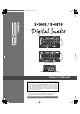
S-1608_e.book 1 ページ 2007年4月23日 月曜日 午後12時57分 S-1608 STAGE UNIT S-0816 FOH UNIT S-4000R REMOTE CONTROLLER Owner’s Manual Before using this unit, carefully read the sections entitled: “IMPORTANT SAFETY INSTRUCTIONS” (Owner’s Manual Pg. 2), “USING THE UNIT SAFELY” (Owner’s Manual Pg. 3–4), and “IMPORTANT NOTES” (Owner’s Manual Pg. 5). These sections provide important information concerning the proper operation of the unit.
S-1608_e.book 2 ページ 2007年4月23日 月曜日 午後12時57分 IMPORTANT SAFETY INSTRUCTIONS WARNING: To reduce the risk of fire or electric shock, do not expose this apparatus to rain or moisture. CAUTION RISK OF ELECTRIC SHOCK DO NOT OPEN ATTENTION: RISQUE DE CHOC ELECTRIQUE NE PAS OUVRIR CAUTION: TO REDUCE THE RISK OF ELECTRIC SHOCK, DO NOT REMOVE COVER (OR BACK). NO USER-SERVICEABLE PARTS INSIDE. REFER SERVICING TO QUALIFIED SERVICE PERSONNEL.
S-1608_e.book 3 ページ 2007年4月23日 月曜日 午後12時57分 THE UNIT SAFELY The symbol alerts the user to important instructions or warnings.The specific meaning of the symbol is determined by the design contained within the triangle. In the case of the symbol at left, it is used for general cautions, warnings, or alerts to danger. Used for instructions intended to alert the user to the risk of death or severe injury should the unit be used improperly.
S-1608_e.book 4 ページ 2007年4月23日 月曜日 午後12時57分 THE UNIT SAFELY 010 ● This unit, either alone or in combination with an amplifier and headphones or speakers, may be capable of producing sound levels that could cause permanent hearing loss. Do not operate for a long period of time at a high volume level, or at a level that is uncomfortable. If you experience any hearing loss or ringing in the ears, you should immediately stop using the unit, and consult an audiologist. ........................................
S-1608_e.book 5 ページ 2007年4月23日 月曜日 午後12時57分 IMPORTANT NOTES In addition to the items listed under “IMPORTANT SAFETY INSTRUCTIONS” and “USING THE UNIT SAFELY” on pages 2 and 3–4, please read and observe the following: Power Supply 301 ● Do not connect this unit to same electrical outlet that is being used by an electrical appliance that is controlled by an inverter (such as a refrigerator, washing machine, microwave oven, or air conditioner), or that contains a motor.
S-1608_e.book 6 ページ 2007年4月23日 月曜日 午後12時57分 Table of Contents IMPORTANT SAFETY INSTRUCTIONS . . . . . . . . . . . . . . . . . . . . . . . . . . . . . . . . . . . . . . . . . . . . . . . . 2 THE UNIT SAFELY . . . . . . . . . . . . . . . . . . . . . . . . . . . . . . . . . . . . . . . . . . . . . . . . . . . . . . . . . . . . . . . 3 IMPORTANT NOTES . . . . . . . . . . . . . . . . . . . . . . . . . . . . . . . . . . . . . . . . . . . . . . . . . . . . . . . . . . . . . 5 1—Introduction. . . . . . . . . . .
S-1608_e.book 7 ページ 2007年4月23日 月曜日 午後12時57分 Table of Contents 6—Using the S-1608/S-0816 System . . . . . . . . . . . . . . . . . . . . . . . . . . . .32 Installation . . . . . . . . . . . . . . . . . . . . . . . . . . . . . . . . . . . . . . . . . . . . . . . . . . . . . . . . . . . . . . . . . . . 32 Installing the Rack-mount kit . . . . . . . . . . . . . . . . . . . . . . . . . . . . . . . . . . . . . . . . . . . . . . . . . . . 32 S-1608 and S-0816 . . . . . . . . . . . . . . . . . . . . . . . . . . .
S-1608_e.book 8 ページ 2007年4月23日 月曜日 午後12時57分 Table of Contents S-1608/S-0816 Input Channel Settings . . . . . . . . . . . . . . . . . . . . . . . . . . . . . . . . . . . . . . . . . . . 51 Selecting a Channel for Editing . . . . . . . . . . . . . . . . . . . . . . . . . . . . . . . . . . . . . . . . . . . . . . . 51 Setting the Preamp Gain. . . . . . . . . . . . . . . . . . . . . . . . . . . . . . . . . . . . . . . . . . . . . . . . . . . . 51 Input Pad . . . . . . . . . . . . . . . . . . . . . . . . . . .
S-1608_e.book 9 ページ 2007年4月23日 月曜日 午後12時57分 Table of Contents Appendices . . . . . . . . . . . . . . . . . . . . . . . . . . . . . . . . . . . . . . . . . . . . . . . .67 Appendix A: Troubleshooting . . . . . . . . . . . . . . . . . . . . . . . . . . . . . . . . . . . . . . . . . . . . . . . . . . . . . 67 S-1608 and S-0816 Units: System Status Indicators . . . . . . . . . . . . . . . . . . . . . . . . . . . . . . . . . . 67 S-4000R Unit: System Status Indicators . . . . . . . . . . . . . . . . . . . . .
S-1608_e.book 10 ページ 2007年4月23日 月曜日 午後12時57分 1 Introduction Welcome Congratulations on your purchase of the RSS S-1608/S-0816 Digital Snake System. Featuring the new REAC (Roland Ethernet Audio Communication) interface, the S-1608/S-0816 System brings the audio snake into the digital age. The S-1608/S-0816 System is designed to be extremely easy to configure and set up, and is at home in any application where multichannel audio transfer is required.
S-1608_e.book 11 ページ 2007年4月23日 月曜日 午後12時57分 1—Introduction Conventions Used in the Manual Names The S-1608/S-0816 Digital Snake System is comprised of three primary components: • S-1608 Stage Unit • S-0816 FOH Unit • S-4000R Remote Controller Throughout the text, the individual components’ names are often shortened, and referred to simply as “S-1608,” “S-0816,” and “S-4000R.” When a procedure or description refers to the entire system, the name “S-1608/S-0816 System” is used.
S-1608_e.book 12 ページ 2007年4月23日 月曜日 午後12時57分 1—Introduction Note, Tip, and Warning Icons Throughout the S-1608/S-0816 Digital Snake Owner’s Manual, you’ll occasionally come across areas highlighted in gray that provide extra information related to the feature or operation described in the main text. The symbols in the left-hand margin define the nature of this extra information.
S-1608_e.book 13 ページ 2007年4月23日 月曜日 午後12時57分 Main Features 2 S-1608/S-0816 System • REAC transmission protocol provides up to 40 channels of 24-bit, 96 kHz audio transfer over a single Cat5e Ethernet cable. The S-1608/S-0816 system can transfer up to 24 channels which are 16 channels from the S-1608 and 8 channels from the S-0816.
S-1608_e.
S-1608_e.book 15 ページ 2007年4月23日 月曜日 午後12時57分 Components and Accessories 3 What’s Included The following components and accessories are included with the S-1608/S-0816 Digital Snake. Main Components 1—S-1608 Stage Unit 1—S-0816 FOH Unit 1—S-4000R Remote Controller Accessories for S-1608 1—AC power supply cord (2.5 meters) 1—REAC connector cover 1—Rack-mounting hardware kit (1—left-side rack mount bracket, 1—Right-side rack mount bracket) 1—AC cord clamp * Attached to the side panel of the S-1608.
S-1608_e.book 16 ページ 2007年4月23日 月曜日 午後12時57分 3—Components and Accessories System Options These items are available system options: 16 • S-4000 Remote Control Software (S-4000 RCS)—Computer control software for PC/Mac (free download from www.rolandsystemsgroup.
S-1608_e.book 17 ページ 2007年4月23日 月曜日 午後12時57分 Panel Descriptions 4 S-1608 Stage Unit / S-0816 FOH Unit S-1608 Front Panel fig.4-01.eps S-0816 Front Panel fig.4-01.
S-1608_e.book 18 ページ 2007年4月23日 月曜日 午後12時57分 4—Panel Descriptions 1—INPUT Connectors Each Input Channel provides balanced input jacks with female XLR connectors. Each input has a variable gain preamp that accepts signals from -65 to +10 dBu (+28 dBu maximum). Additionally, there are three status indicators for each input: • CLIP—lights red when the input signal exceeds 0 dB (after A/D conversion). • SIG—lights green when the input signal is greater than -40 dB (after A/D conversion).
S-1608_e.book 19 ページ 2007年4月23日 月曜日 午後12時57分 4—Panel Descriptions 5—Digital Out Connector (Optical Type) This optical type digital out connector outputs the audio signal input to INPUT 1/2 of the S-1608/S0816. 6—[MUTE ALL OUTPUTS] Button The [MUTE ALL OUTPUTS] button is a momentary switch used to temporarily mute the S-1608/ S-0816 System’s audio outputs. This allows for noise-free connection of audio input sources. Press and hold the [MUTE ALL OUTPUTS] button. After approximately 1.
S-1608_e.book 20 ページ 2007年4月23日 月曜日 午後12時57分 4—Panel Descriptions S-1608/S-0816 Side Panel fig.4-02.eps 1—POWER AC INPUT Jack Connect one end of the supplied AC power cord to a grounded AC outlet, and the other end to the POWER AC INPUT jack to provide power for the S-1608’s or S-0816’s internal power supply. Use the cord clamp on the side panel to prevent the power cord from being accidentally pulled out. Use only the supplied power cord to prevent damage to the S-1608/S-0816.
S-1608_e.book 21 ページ 2007年4月23日 月曜日 午後12時57分 4—Panel Descriptions 4—Air Intake Vents 5—Cooling Fan Exhaust Vents The S-1608/S-0816 contains cooling fans that prevent the unit from overheating. The air intake vents provide fresh air for the cooling fans and the fans expel hot air through these vents. Be sure never to block the cooling fan exhaust vents and air intake vents. Doing so may cause the S-1608/S-0816 to overheat and be damaged.
S-1608_e.book 22 ページ 2007年4月23日 月曜日 午後12時57分 4—Panel Descriptions S-4000R Remote Controller S-4000R Front Panel fig.4-05.eps 1—Signal Status Indicators These indicator lights show signal status for each of the S-1608/S-0816 System’s 24 input channels. • CLIP—lights red when the input signal exceeds 0 dB (after A/D conversion). Once a CLIP indicator lights, it stays lit until cleared with the [CLIP CLEAR / ENTER] button.
S-1608_e.book 23 ページ 2007年4月23日 月曜日 午後12時57分 4—Panel Descriptions 4—[CLIP CLEAR / ENTER] Button The [CLIP CLEAR / ENTER] button is a dual-function button. It’s used to: • clear the clip indicators—When an input signal connected to one of the system’s audio inputs exceeds 0 dB (in the digital domain), the corresponding clip indicators on the S-4000R light, and the [CLIP CLEAR / ENTER] button flashes. To turn off all clip lights, press [CLIP CLEAR / ENTER] so that it stops flashing.
S-1608_e.book 24 ページ 2007年4月23日 月曜日 午後12時57分 4—Panel Descriptions 9—[PHANTOM +48 V] Button Each S-1608/S-0816 System’s input channel can provide +48 V phantom power to connected devices that require it (such as condenser microphones and active direct boxes). Press the [PHANTOM +48 V] button so its indicator lights to turn on phantom power on the currently selected input channel. To turn off phantom power, select the desired channel and press [PHANTOM +48 V] so its indicator goes out.
S-1608_e.book 25 ページ 2007年4月23日 月曜日 午後12時57分 S-1608/S-0816 System Overview 5 Concept The S-1608/S-0816 System brings the digital revolution to the world of audio snakes. Using computer networking technology, the system allows you to transfer 24 channels of high-quality audio over an extremely long distance on a single lightweight cable. The digital advantage also brings with it easy installation, low cost, portability, and pain-free expansion. The Old School...
S-1608_e.book 26 ページ 2007年4月23日 月曜日 午後12時57分 5—S-1608/S-0816 System Overview Things to Know About REAC About At the heart of the S-1608/S-0816 System is the REAC (Roland Ethernet Audio Communication) interface. This proprietary protocol is based on the Ethernet technology that’s used in computer networks, and allows for the transfer of up to 40 channels of digital audio over a single Cat5e Ethernet cable.
S-1608_e.book 27 ページ 2007年4月23日 月曜日 午後12時57分 5—S-1608/S-0816 System Overview In the following cases, either a crossover or a straight-through cable can be used. • When directly connecting the S-1608 and S-0816 via REAC • When using the S-4000-SP REAC splitter to extend the REAC cable or to split connect a separate S-1608 or S-0816 Ethernet connection standards recommend using straight-through cables to connect devices to the ports on a switching hub, and crossover cables when connecting hub-to-hub.
S-1608_e.book 28 ページ 2007年4月23日 月曜日 午後12時57分 5—S-1608/S-0816 System Overview About Ethernet Switching Hubs An Ethernet switching hub—sometimes referred to simply as a “switch”—is an interface that allows multiple devices (called “nodes” in Ethernet lingo) to communicate with each other in an Ethernet network. The switching hub has multiple ports with RJ45 receptacles, and each network device is connected to one of these ports.
S-1608_e.book 29 ページ 2007年4月23日 月曜日 午後12時57分 5—S-1608/S-0816 System Overview To be used in a REAC system, an Ethernet switching hub must meet the following requirements: • 1000BASE-T transmission speed (IEEE802.3ab, Gigabit Ethernet) • Support for 100BASE-TX devices (IEEE802.3u, Fast Ethernet) • Bidirectional (full-duplex) communication Connect REAC devices only to switching hub ports that support 100BASE-TX. The transmission protocol for REAC is based on 100BASE-TX (Fast Ethernet).
S-1608_e.book 30 ページ 2007年4月23日 月曜日 午後12時57分 5—S-1608/S-0816 System Overview The System Components: A Closer Look S-1608 Stage Unit The S-1608 is the stage connection interface for the S-1608/S-0816 System. Its box design supports 24 channels of audio input and output (I/O). As standard, it comes in a 16x8 configuration—16 audio inputs and 8 audio outputs. S-0816 FOH Unit The S-0816 is the front-of-house (FOH) connection interface for the S-1608/S-0816 System.
S-1608_e.book 31 ページ 2007年4月23日 月曜日 午後12時57分 5—S-1608/S-0816 System Overview S-4000R Remote Controller The S-4000R functions as a remote controller for the S-1608/S-0816 System. It can be connected to either the S-1608 or S-0816 unit, whichever is most convenient for you. • Input channel control—The S-4000R provides control over the S-1608/S-0816 System’s input channels. This includes preamp gain adjustment, phantom power and pad on/off status, and channel linking.
S-1608_e.book 32 ページ 2007年4月23日 月曜日 午後12時57分 Using the S-1608/S-0816 System 6 Installation Installing the Rack-mount kit S-1608 and S-0816 The S-1608 and S-0816 can be used in a free standing configuration, or rack-mounted using the installed rack-mount kit. Precautions for Rack Mounting • When mounting the S-1608 or S-0816 in a rack, observe the following precautions to ensure efficient and effective cooling. - - Ensure that the location provides good air flow and ventilation.
S-1608_e.book 33 ページ 2007年4月23日 月曜日 午後12時57分 6—Using the S-1608/S-0816 System 3. Using the 4 screws you removed in Step 2, install the rack-mount bracket as shown. fig.6-03.eps S-4000R The S-4000R Remote Controller is designed for handheld or desktop use. If desired, it can be rackmounted by installing the included rack-mount brackets. Use the following procedure to install the rack-mount brackets on the S-4000R. 1. Disconnect the RS-232C cable from the S-4000R unit. 2.
S-1608_e.book 34 ページ 2007年4月23日 月曜日 午後12時57分 6—Using the S-1608/S-0816 System Using the AC Cord Clamp The S-1608 and S-0816 units have AC cord clamps to prevent the cord from being pulled out accidentally. 1. Remove only the screws shown in the following diagram (2 screws total), and detach the AC cord clamp. 2. As shown in the figure, clamp the AC power cord with the AC Cord Clamp, and secure with the screws (2) removed in Step 1. fig.6-01.
S-1608_e.book 35 ページ 2007年4月23日 月曜日 午後12時57分 6—Using the S-1608/S-0816 System Installing the Included Ferrite Core on Ethernet Cables One ferrite core is included with both the S-1608 and S-0816 for installation on Ethernet cables. Install a ferrite core on REAC cable SC-W100S (sold separately) or Ethernet cable near the RJ45 plug that will be connected to a REAC port. For REAC connections, make sure to attach ferrite cores to your cables.
S-1608_e.book 36 ページ 2007年4月23日 月曜日 午後12時57分 6—Using the S-1608/S-0816 System Using the REAC Connector Cover (S-1608 and S-0816) The REAC port on the S-1608 and S-0816 units feature rugged Neutrik® EtherCon® connectors. As discussed in Chapter 5, they can accept either standard RJ45 plugs or RJ45 plugs housed in EtherContype connectors. When using an Ethernet cable with standard RJ45 plugs, fit the included REAC connector cover on the REAC port as shown. fig.6-09.
S-1608_e.book 37 ページ 2007年4月23日 月曜日 午後12時57分 6—Using the S-1608/S-0816 System Connection Overview To prevent malfunction and/or damage to speakers or other devices, always turn down the volume, and turn off the power on all devices before making any connections. fig.6-14.
S-1608_e.book 38 ページ 2007年4月23日 月曜日 午後12時57分 6—Using the S-1608/S-0816 System Setting the REAC Mode fig.6-15.eps The S-1608 and S-0816 each feature a [REAC MODE] switch. This switch sets the REAC behavior of each device, and determines how audio is transferred throughout the system. Each unit’s [REAC MODE] switch must be set properly for correct system operation. The [REAC MODE] switch has three different settings: • • • M—configures the unit as a Master REAC device.
S-1608_e.book 39 ページ 2007年4月23日 月曜日 午後12時57分 6—Using the S-1608/S-0816 System Setting the [REAC MODE] Switches fig.6-16.eps The [REAC MODE] switch on the S-1608/S-0816 is recessed from the front panel so that its setting can’t be changed inadvertently. To change the switch setting, use a blunt-tipped instrument such as a ball-point pen, mechanical pencil, etc. With their power off, set the units as follows: 1. On the S-1608, set the [REAC MODE] switch to M. 2.
S-1608_e.book 40 ページ 2007年4月23日 月曜日 午後12時57分 6—Using the S-1608/S-0816 System Component Connections AC Power Connections On the S-1608: • Connect one end of the supplied AC power cord to a grounded AC outlet, and the other end to the POWER AC INPUT jack to provide power for the S-1608’s internal power supply. On the S-0816: • Connect one end of the supplied AC power cord to a grounded AC outlet, and the other end to the POWER AC INPUT jack to provide power for the S-0816’s internal power supply.
S-1608_e.book 41 ページ 2007年4月23日 月曜日 午後12時57分 6—Using the S-1608/S-0816 System REAC Cable Length Extension If necessary, the REAC cable length can be extended by placing a REAC Splitter S-4000-SP or Ethernet switching hub in-line to refresh the REAC signal. Multiple splitters and switching hubs can be used (up to four total), with a maximum cable length of 100 meters between hubs. (Total cable length with four switching hubs: 500 meters.) See Chapter 5 for a discussion about Ethernet cables.
S-1608_e.book 42 ページ 2007年4月23日 月曜日 午後12時57分 6—Using the S-1608/S-0816 System Notes About Handling Cat5e Cables (REAC Cables) • Do not subject the Cat5e cable to stress or physical shock. • Do not bend the Cat5e cable within a range of 25 mm. • Do not fasten Cat5e cables in a tight bundle. • Avoid laying multiple Cat5e cables in a parallel orientation over long distances. • Avoid laying Cat5e cables near noise sources (AC power cables, motors, fluorescent lighting, etc.).
S-1608_e.book 43 ページ 2007年4月23日 月曜日 午後12時57分 6—Using the S-1608/S-0816 System Audio Connections When making audio input connections with the S-1608 and/or S-0816 units powered on, always press and hold the [MUTE ALL OUTPUTS] button on the respective unit’s front panel so its indicator lights. This will mute the sound coming from the S-1608/S-0816 System’s audio outputs and prevent possible damage to connected speakers and other devices. See Page 48 for more information about [MUTE ALL OUTPUTS].
S-1608_e.book 44 ページ 2007年4月23日 月曜日 午後12時57分 6—Using the S-1608/S-0816 System S-1608/S-0816 Audio Inputs The S-1608’s (S-0816’s) audio inputs are used to send source audio signals to the S-0816’s (S-1608’s) audio outputs. Connect the output of balanced audio devices (microphones, instrument outputs, etc.) to the balanced audio inputs on the S-1608 (S-0816) front panel.
S-1608_e.book 45 ページ 2007年4月23日 月曜日 午後12時57分 6—Using the S-1608/S-0816 System Input Status Indicators Each S-1608/S-0816 input has three status indicators: fig.6-28.eps • +48V—lights orange when +48 V phantom power is supplied from the channel. • CLIP—lights red when the input signal exceeds 0 dB. • SIG—lights green when the input signal is greater than -40 dB. The CLIP and SIG signal status indicators represent the signal level in the digital domain (post-A/D conversion).
S-1608_e.book 46 ページ 2007年4月23日 月曜日 午後12時57分 6—Using the S-1608/S-0816 System Powering Up Powering Up Connect and power up devices in the following order: Turn on power to your various devices in the order specified. By turning on devices in the wrong order, you risk causing malfunction and/or damage to speakers and other devices. Additionally, in each of the following steps, allow each piece of equipment to finish its power-up sequence before proceeding to the next step. 1.
S-1608_e.book 47 ページ 2007年4月23日 月曜日 午後12時57分 6—Using the S-1608/S-0816 System System Status Indicators The S-1608, S-0816, and S-4000R have system status indicators that allow you to monitor the integrity of the component connections when the system is powered up. Power Indicators S-1608/S-0816 fig.6-30.eps This indicator lights when the unit is receiving power from its internal power supply. S-4000R fig.6-31.
S-1608_e.book 48 ページ 2007年4月23日 月曜日 午後12時57分 6—Using the S-1608/S-0816 System Muting the System Outputs fig.6-35.eps Ordinarily, when plugging and unplugging devices to and from the audio inputs and outputs on the S-1608 and S-0816 units, the volume of all devices connected to the S-1608/S-0816 System’s audio outputs should be lowered. However, this may be impractical in some circumstances. In such cases, you can temporarily mute the sound coming from the S-1608/S-0816 System’s audio outputs.
S-1608_e.book 49 ページ 2007年4月23日 月曜日 午後12時57分 6—Using the S-1608/S-0816 System Using the S-4000R Remote Controller When the S-4000R is connected to the S-1608/S-0816 System, you can: • control S-1608 and S-0816 input channel functions—including preamp gain, pad, and phantom power. • monitor signal level status of the system’s input channels—including the presence of signal and overload (clip). • monitor the level of the system’s input channels—using the eight-segment LED input meter.
S-1608_e.book 50 ページ 2007年4月23日 月曜日 午後12時57分 6—Using the S-1608/S-0816 System Monitoring Input Signals Signal Status Indicators The S-4000R has two rows of signal status indicators that allow you to monitor the signal activity on the S-1608/S-0816 System’s 24 audio inputs (1–16 for the S-1608 and 17–24 for the S-0816). fig.6-37.eps S-1608 INPUT 1–16 S-0816 INPUT 1–8 Not used with the S-1608/S-0816 system. • SIG—lights green when the input signal level is higher than -40 dB on a particular channel.
S-1608_e.book 51 ページ 2007年4月23日 月曜日 午後12時57分 6—Using the S-1608/S-0816 System S-1608/S-0816 Input Channel Settings With the S-4000R unlocked, use the following procedures to adjust settings on the S-1608 and S-0816 input channels. To retain your changes to the S-1608/S-0816 system’s input channel settings, lock the S-4000R before powering down the S-1608/S-0816 System. When the system is powered up, the settings will return to the state they were in when the S-4000R was last locked.
S-1608_e.book 52 ページ 2007年4月23日 月曜日 午後12時57分 6—Using the S-1608/S-0816 System Input Pad fig.6-42.eps Each S-1608/S-0816 system’s input channel features a switchable input pad. When the pad is engaged, the channel’s input sensitivity is reduced by 20 dB. Use the pad when connecting a “hot” audio source to an S-1608/S0816 system’s input—one whose signal exceeds 0 dB (and causes the clip indicator to light) even when the channel’s [GAIN] knob is at its lowest setting.
S-1608_e.book 53 ページ 2007年4月23日 月曜日 午後12時57分 6—Using the S-1608/S-0816 System Stereo Link The Stereo Link function allows you to link odd/even adjacent S-1608/S-0816 system’s input channel pairs (1/2, 3/4, etc.). When channels are linked, gain and pad settings made on one channel of the linked pair will be duplicated on the other. This can be convenient when audio devices with stereo outputs are connected to the S-1608 or S-0816.
S-1608_e.book 54 ページ 2007年4月23日 月曜日 午後12時57分 6—Using the S-1608/S-0816 System Memory Function The S-1608/S-0816 system features 10 user-storable memory presets. A memory preset contains channel settings (preamp gain, pad, phantom power, and stereo link) for all of the S-1608/S-0816 system’s 24 input channels. Using memory presets, you can quickly reconfigure the S-1608/S-0816 for frequently used audio input setups.
S-1608_e.book 55 ページ 2007年4月23日 月曜日 午後12時57分 Advanced Use 7 Using Two S-4000R Units in a Single S-1608/S-0816 System As discussed in Chapter 6, the S-4000R can be connected to either the S-1608 or S-0816. However, if you have a second S-4000R (available separately), you can connect one to each unit. This allows for control and signal monitoring of the S-1608/S-0816 System at the location of either unit. fig.7-01.
S-1608_e.book 56 ページ 2007年4月23日 月曜日 午後12時57分 7—Advanced Use Computer Control (S-4000 RCS) The S-4000 Remote Control Software (S-4000 RCS) allows for the remote control and monitoring of the S-1608/S-0816 System from a personal computer equipped with an RS-232C port. Functionally, using the S-4000 RCS is similar to using the S-4000R Remote Controller, but with the conveniences provided by a personal computer.
S-1608_e.book 57 ページ 2007年4月23日 月曜日 午後12時57分 7—Advanced Use Traditionally, when using an analog snake system, audio splits are taken directly at the source. This requires the use of expensive and bulky transformer-based audio splitters, as well as an additional analog snake for each split destination.
S-1608_e.book 58 ページ 2007年4月23日 月曜日 午後12時57分 7—Advanced Use Split Connection Overview fig.7-02.
S-1608_e.book 59 ページ 2007年4月23日 月曜日 午後12時57分 7—Advanced Use Notes on Split Setups • A Split REAC device can only receive audio from the Master REAC device—it can’t receive audio from a Slave REAC device (or another Split device). • When a unit is set as a Split REAC device, its audio inputs are disabled. • An S-4000R can be connected to the REMOTE connector on a Split REAC device.
S-1608_e.book 60 ページ 2007年4月23日 月曜日 午後12時57分 7—Advanced Use REAC Connections For the REAC connections: • Using Cat5e cables, connect the REAC port on the S-1608/S-0816 units to ports on the REAC splitter S-4000-SP or the switching hub. fig.7-03.
S-1608_e.book 61 ページ 2007年4月23日 月曜日 午後12時57分 7—Advanced Use Audio Connections and Power Up Connect and power up devices in the following order: In each of the following steps, allow each piece of equipment to finish its power-up sequence before proceeding to the next step. 1. Connect the system components as described here and in Chapter 6. 2. Connect audio devices to the Master and Slave REAC devices’ inputs and outputs. 3. Connect audio devices to the Split REAC devices’ outputs.
S-1608_e.book 62 ページ 2007年4月23日 月曜日 午後12時57分 8 Applications 16x8 System fig.8-01.
S-1608_e.book 63 ページ 2007年4月23日 月曜日 午後12時57分 8—Applications 16x8 System with 16 Channel Split fig.8-02.
S-1608_e.book 64 ページ 2007年4月23日 月曜日 午後12時57分 8—Applications 32x16 System fig.8-03.
S-1608_e.book 65 ページ 2007年4月23日 月曜日 午後12時57分 8—Applications 32x16 System with 32 Channel Split fig.8-04.
S-1608_e.book 66 ページ 2007年4月23日 月曜日 午後12時57分 8—Applications ][ Connection to S-4000S/S-4000H It’s possible to use the S-1608/S-0816 with S-4000S or S-4000H in the following configuration. The S-4000S input/output module (SI-AD4, SI-AES4/SO-DA4, SO-AES4) is set up as shown below. You should not attach nor remove the module. Be sure to consult with the nearest Roland Service Center. Please visit www.rolandsystemsgroup.net for the latest information about the S-1608/S-0816 System.
S-1608_e.book 67 ページ 2007年4月23日 月曜日 午後12時57分 Appendices Appendix A: Troubleshooting The components in the S-1608/S-0816 System provide many different indicators that show the current system status. Additionally, the units provide error indicators that let you know whenever a potentially serious problem is detected in the system. The following tables show the meaning of the various status and error indicators, and suggest actions for troubleshooting and safe system operation.
S-1608_e.
S-1608_e.book 69 ページ 2007年4月23日 月曜日 午後12時57分 Appendices Appendix B: Connector Information Cat5e Ethernet Cable Wiring (RJ45-type Connectors) Cat5e Crossover Wiring (REAC cable: SC-W100S) fig.app-01.eps TX+ 1 1 TX+ TX- 2 2 TX- RX+ 3 3 RX+ 4 4 5 5 6 6 7 7 8 8 RX- RX- Note: Pins 4, 5, 7, and 8 are not used in this application, but may be wired in the cable as shown. Cat5e Straight-Through Wiring fig.app-02.
S-1608_e.book 70 ページ 2007年4月23日 月曜日 午後12時57分 Appendices RS-232C (REMOTE) Connector (D-Sub, DB-9-type) Maximum recommended cable length: 15 meters. Pin Number Signal Name 1 NC 2 TxD (Data Out) 3 RxD (Data In) 4 NC 5 GND 6 +5 V 7 Short to Pin 8 8 Short to Pin 7 9 Pin Connection Included RS-232C cable 4 2 3 5 9 7 8 NC 1 6 1 2 3 4 5 6 7 8 9 1 2 3 4 5 6 7 8 9 Note: Pins 1, 4 and 9 are not used in this application, but may be wired in the cable as shown.
S-1608_e.book 71 ページ 2007年4月23日 月曜日 午後12時57分 Appendices Appendix C: Ethernet Switching Hub Requirements To be used in a REAC system, an Ethernet switching hub must meet the following requirements: • 1000BASE-T transmission speed (IEEE802.3ab, Gigabit Ethernet) • Support for 100BASE-TX devices (IEEE802.3u, Fast Ethernet) • Bi-directional (full-duplex) communication Connect REAC devices only to switching hub ports that support 100BASE-TX.
S-1608_e.book 72 ページ 2007年4月23日 月曜日 午後12時57分 Appendices Appendix D: Specifications Specifications: S-1608 STAGE UNIT Number of Channels 16 in 8 out AD Conversion Sample Rate: 96.0 kHz Signal Processing: 24 bits DA Conversion Sample Rate: 96.0 kHz Signal Processing: 24 bits Frequency Response -2 dB / +0 dB (@ +4 dBu, 20 Hz to 20 kHz) Total Harmonic Distortion + Noise 0.
S-1608_e.book 73 ページ 2007年4月23日 月曜日 午後12時57分 Appendices Specifications: S-0816 FOH UNIT Number of Channels 8 in 16 out AD Conversion Sample Rate: 96.0 kHz Signal Processing: 24 bits DA Conversion Sample Rate: 96.0 kHz Signal Processing: 24 bits Frequency Response -2 dB / +0 dB (@ +4 dBu, 20 Hz to 20 kHz) Total Harmonic Distortion + Noise 0.05 % or less (Pad: On, Input Gain: +4 dBu, 22 Hz to 20 kHz) Dynamic Range 110 dB Cross Talk -80 dB or less (Input Gain: +4 dBu, typ.
S-1608_e.book 74 ページ 2007年4月23日 月曜日 午後12時57分 Appendices [Specifications: S-4000R REMOTE CONTROLLER Connectors Remote Connector: 1 (RS-232C, DB-9-type) Indicators CLIP Indicators (1–40) SIG Indicators (1–40) POWER Indicator REAC Indicator CTRL Indicator Level Meter CHANNEL Display (8 segments 2 digits.) GAIN Indicators (15 steps) Memory 10 memory presets Power Supply Supplied from connected device (S-1608 or S-0816, through the remote cable) Dimensions 215 (W) x 87 (D) x 54.
S-1608_e.book 75 ページ 2007年4月23日 月曜日 午後12時57分 Appendices Appendix E: Dimensions Dimensions: S-1608 Note: Dimensions are shown in millimeters. 135 fig.app-12.eps 135 177 401 177 101.
S-1608_e.book 76 ページ 2007年4月23日 月曜日 午後12時57分 Appendices Dimensions: S-0816 Note: Dimensions are shown in millimeters. 135 fig.app-13.eps 135 177 401 177 101.
S-1608_e.book 77 ページ 2007年4月23日 月曜日 午後12時57分 Appendices Dimensions: S-4000R Note: Dimensions are shown in millimeters. fig.app-14.eps 60.9 54.3 89.2 87.8 215 54.
S-1608_e.
S-1608_e.book 79 ページ 2007年4月23日 月曜日 午後12時57分 For EU Countries This product complies with the requirements of European Directives EMC 89/336/EEC and LVD 73/23/EEC. For the USA FEDERAL COMMUNICATIONS COMMISSION RADIO FREQUENCY INTERFERENCE STATEMENT This equipment has been tested and found to comply with the limits for a Class B digital device, pursuant to Part 15 of the FCC Rules. These limits are designed to provide reasonable protection against harmful interference in a residential installation.
S-1608_e.book 80 ページ 2007年4月23日 月曜日 午後12時57分 Information When you need repair service, call your nearest Roland Service Center or authorized Roland distributor in your country as shown below. ASIA INDONESIA PT. Citra IntiRama JL. Cideng Timur No. 15J-15O Jakarta Pusat INDONESIA TEL: (021) 632-4170 EUROPE AUSTRIA/BELGIUM/ FRANCE/GERMANY/ HOLLAND/ LUXEMBOURG/ PORTUGAL/SPAIN/ SWITZERLAND Roland Iberia, S.L. TAIWAN ROLAND TAIWAN ENTERPRISE CO., LTD. Room 5, 9fl. No. 112 Chung Shan N.Road Sec.