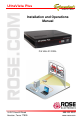
UltraVista Plus Installation and Operations Manual P/N VWL-D122DDL 10707 Stancliff Road Houston, Texas 77099 800-333-9343 www.rose.
LIMITED WARRANTY Rose Electronics® warrants the UltraVista™ Plus to be in good working order for one year from the date of purchase from Rose Electronics or an authorized dealer. Should this product fail to be in good working order at any time during this one-year warranty period, Rose Electronics will, at its option, repair or replace the Unit as set forth below. Repair parts and replacement units will be either reconditioned or new. All replaced parts become the property of Rose Electronics.
TABLE of CONTENTS CONTENTS PAGE # Disclaimer.......................................................................................................1 System Introduction........................................................................................1 Product Registration .......................................................................................1 About this manual...........................................................................................1 Features .........................
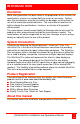
INTRODUCTION Disclaimer While every precaution has been taken in the preparation of this manual, the manufacturer assumes no responsibility for errors or omissions. Neither does the manufacturer assume any liability for damages resulting from the use of the information contained herein. The manufacturer reserves the right to change the specifications, functions, or circuitry of the product without notice.
Features Single or dual link DVI input support Max output resolution 2048 x 2048 Full bezel width and height correction Splits a single DVI input into four independent outputs Output monitors can be DVI or Analog RGB Each output monitor can display any selected area of the input image Auto-detection of input resolution and output monitor native resolution Default setting displays ¼ of the input signal on each output monitor in a 2x2 array.
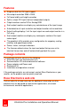
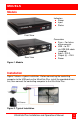
MODELS Models Indicators Power Input Status Front View Rear View Connectors Sync – For future enhancements USB – to PC via USB A/B cable (supplied) Input – DVI-D Output (4) – DVI-I Power Figure 1. Models Installation Figure 2 shows a typical installation. Before connecting the controlling computer to the USB port on the UltraVista Plus, install the provided drivers first, then connect the controlling computer to the UltraVista Plus. DVI Source Figure 2.
Unit Installation Installing the UltraVista Plus is a straight forward procedure. First: Make sure that the power supply for the DVI source is disconnected Connect a DVI cable from the DVI source to the DVI-D input connector on the rear panel of the UltraVista Plus Connect four displays to the DVI-I input connectors on the rear panel Connect the 5VDC power adapter to the UltraVista Plus power input jack and switch on the power.
Configuring DVI Input resolution Because the timings and resolution of the DVI input are set by the DVI source machine, the UltraVista Plus can only configure this indirectly by presenting a programmable “Preferred Mode” as part of its EDID (Extended Display Identification Data).
Selecting the Regions to Be Displayed Each output of the UltraVista Plus can take its display data from any arbitrary rectangular region of the captured input image. The factory default for these cropping rectangles configures the four monitors to display a quarter of the input as a 2x2 array, and these proportions are maintained across different input resolutions.
Control Application UltraVista Plus Control Application Application Installation Note: Do not connect the UltraVista Plus to the controlling computer’s USB port until the driver installation is complete. Locate the Install folder on the supplied CD and run the install.exe program. The installation is a standard windows type installation, follow the installation wizard instructions. During installation a warning message is displayed stating that the driver does not have Windows® Logo accreditation.
The main control application window is divided into the following groups: Connection Diagram Device DVI-D Input Input capture region Monitor Outputs Connection diagram The connection diagram shows a view of the rear panel of the UltraVista Plus. Device section The unique USB device name that is connected is displayed in the Device group. It is possible to associate a more user friendly name such as “First Four Outputs”.
DVI-D Input section The DVI-D Input group displays the current DVI mode that is being captured (if any) and the preferred mode that has been programmed into the UltraVista Plus’s EDID. Use the Modify button to update the EDID. The small square to the left of the current input resolution indicates whether the UltraVista Plus has genlocked to the input source.
The DVI-D Input dialog displays the resolution of the current mode for reference and allows the timings of the EDID preferred mode to be edited. The dialog supports standard timing formulae such as: VESA CVT CVT Reduced Blanking SMPTE (for HD modes) VESA GTF Custom Selecting Auto from the drop down list will typically default to the VESA CVT algorithm. This best matches typical standard VESA output modes. The CVT Reduced Blanking is recommended to minimize dot clocks and maximize DVI cable lengths.
Selecting Custom allows the timing parameters to be edited. It should be noted that you will need to select between definition of Pixel Clock or Vertical Refresh since these are mutually excusive parameters. Once edited, clicking OK writes the preferred mode into the EDID but may not normally affect the input mode that is being captured.
Predifined Regions For ease of use, there are preset buttons to select the two most popular configurations: Quarter or Replicate. Quarter The first monitor displays the top left hand corner of the input image, the second monitor the top right, the third the bottom left etc. This mode of operation can be used to drive four monitors in a 2x2 arrangement from a single high resolution input. Replicate Each output displays the entire input image.
such as rotation or flipping applied to it (after cropping) in order to support different output monitor orientations. Please note that there may be instances where a setting stored in nonvolatile memory which was valid when it was stored (ie the scale factors from input to output were 1:1 or greater) may subsequently require downscaling if the resolution of the input increases. In this case the firmware will adjust the scaling factors to give a 1:1 crop of the input, centered on the original region.
Individual monitor outputs can be configured by clicking on the corresponding Modify button. This will bring up a timing dialog similar to that of the input timings. This dialog is shown below.
The source of mode selection controls whether the x4 output should take its timing values and resolution from the preferred mode of the monitor that is connected, or use its internally programmed ‘default’ mode. Please note that only the internal default timings can be edited in this dialog.
If Use the Monitors Preferred Mode is selected, but no valid EDID can be read from the attached monitor, then the x4 firmware will program the output to use the default mode timings. The rest of the dialog is identical to that for setting the Input timings, with the exception that for the output monitors it is possible to select Analog RGB (“VGA”) output as well as DVI. All modifications to the Output… settings can be save as a .vqs file, removing the requirement to input the same settings again.
SAFETY Product Safety The UltraVista Plus has been tested for conformance to safety regulations and requirements, and has been certified for international use. Like all electronic equipment, the UltraVista Plus should be used with care. To protect yourself from possible injury and to minimize the risk of damage to the Unit, read and follow these safety instructions. Follow all instructions and warnings marked on this Unit. Except where explained in this manual, do not attempt to service this unit yourself.
MAINTENANCE and SUPPORT Service Information Maintenance and Repair This Unit does not contain any internal user-serviceable parts. In the event a Unit needs repair or maintenance, you must first obtain a Return Authorization (RA) number from Rose Electronics or an authorized repair center. This Return Authorization number must appear on the outside of the shipping container. See Limited Warranty for more information.
Appendices Appendix A – Specifications Part Number P/N VWL-D122DDL Resolution 2048 x 2048 (up to 2.5Mpixel) Single Link DVI or Analog RGB output Up to 165 Mpixels/s Dual Link DVI capture Up to 330 Mpixels/s USB 2.0 Full speed (12Mbits/s) Power 100-240VAC adapter to 5VDC, 11W Operating Temperature 32° - 96°F (0° - 35°C) Up Scaling 64x original surface area Input surface 4k x 4k Max MTBF 50,000 hrs. Dimensions Width Depth Height 9.25” (235mm) 6.90” (175mm) 1.
〒103ー0014 東京都中央区日本橋蛎殻町1ー16ー11 TEL : 03ー3668ー8089 FAX:03ー3668ー9872 URL : www.cybernetech.co.