
Instruction manual
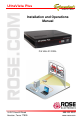


4 UltraVista Plus Installation and Operations Manual
Unit Installation
Installing the UltraVista Plus is a straight forward procedure. First:
Make sure that the power supply for the DVI source is disconnected
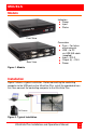
Connect a DVI cable from the DVI source to the DVI-D input
connector on the rear panel of the UltraVista Plus
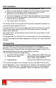
Connect four displays to the DVI-I input connectors on the rear panel
Connect the 5VDC power adapter to the UltraVista Plus power input
jack and switch on the power.
Last, power up the DVI source
The Power LED on the front panel will illuminate to indicate that power has
successfully been applied to the unit.
The UltraVista Plus has an internal processor that will continuously monitor
the DVI input signal, and the input LED will illuminate when a valid and
stable input is detected.
If the Input LED is not illuminated, the UltraVista Plus cannot detect a valid
DVI input source.
During operation, the UltraVista Plus is able to adjust its internal operation to
maintain the programmed output proportions even when the input resolution
changes.
Configuration
The UltraVista Plus stores a number of parameters to configure its
operation. This allows it to operate stand alone in a very flexible manner.
The configurations affect the input and output display modes as well as the
required partitioning of the input image between monitors.
The UltraVista Plus default configuration is:
Input EDID Preferred Mode: 1920 x 1080 x 60Hz (SMPTE timings)
Output monitor mode: Use Monitor Preferred Mode Default :
1920 x 1080 x 60Hz (SMPTE)
Cropping Mode: 2x2 equal split (960x540) No Rotation
These default settings can be changed using the provided UltraVista Plus
control application. This is executed from a computer connected to the USB
port on the UltraVista Plus. The application can be run on any Windows®
platform. (See the Control Application section for additional information)