Reference Manual 00809-0100-4480, Rev AA September 2020 Rosemount™ 1408H Level Transmitter Non-Contacting Radar
Safety messages NOTICE Read this manual before working with the product. For personal and system safety, and for optimum product performance, ensure you thoroughly understand the contents before installing, using, or maintaining this product. For technical assistance, contacts are listed below: Customer Central Technical support, quoting, and order-related questions.
Reference Manual 00809-0100-4480 Contents September 2020 Contents Chapter 1 Introduction.............................................................................................................. 5 1.1 Using this manual........................................................................................................................ 5 1.2 Product recycling/disposal...........................................................................................................
Contents September 2020 Reference Manual 00809-0100-4480 7.6 Service support..........................................................................................................................69 Appendix A Specifications and reference data............................................................................. 71 A.1 Performance specifications........................................................................................................71 A.2 Functional specifications................
Reference Manual 00809-0100-4480 Introduction September 2020 1 Introduction 1.1 Using this manual The sections in this manual provide information on installing, operating, and maintaining the Rosemount™ 1408H Level Transmitter – Non-Contacting Radar. The sections are organized as follows: Transmitter overview provides an introduction to theory of operation, a description of the transmitter, information on typical applications, and process characteristics.
Introduction September 2020 6 Reference Manual 00809-0100-4480 Rosemount 1408H Level Transmitter
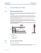
Reference Manual 00809-0100-4480 Transmitter overview September 2020 2 Transmitter overview 2.1 Measurement principle The Rosemount 1408H is a transmitter for continuous level measurements in the hygienic industry. The measurement principle is fast-sweep Frequency Modulated Continuous Wave (FMCW). The transmitter continuously emits signal sweeps with a constantly varying frequency towards the product surface.
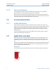
Transmitter overview September 2020 2.2.2 Reference Manual 00809-0100-4480 Foam and turbulence Foaming liquids or turbulence may cause weak and varying surface echo amplitudes. Surface turbulence is not normally a problem unless it is excessive. Measurement in foamy applications depends largely on the foam properties. When the foam is light and airy, the actual product level is measured. For heavy and dense foam, the transmitter may measure the level of the foam’s upper surface. 2.
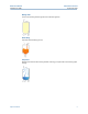
Reference Manual 00809-0100-4480 Transmitter overview September 2020 Mixing tanks Ensure correct filling and storage levels in tanks with agitators. Batch filling Optimize the batch filling process. CIP process Reliable level measurement during and after cleaning, plus optimization of cleaning agent storage.
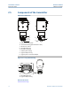
Transmitter overview September 2020 2.5 Reference Manual 00809-0100-4480 Components of the transmitter Figure 2-2: Components A B C D D H E F A. B. C. D. E. F. G. H. G M12 connector (A-coded) Transmitter housing (polished stainless steel) Wrench size: 39 mm DIN 3869 profile ring ISO 228/1-G1 thread Antenna (PTFE sealing) Hygienic adapter O-ring Hygienic process connection adapter Figure 2-3: O-ring and Profile Ring A B A. DIN 3869 profile ring B.
Reference Manual 00809-0100-4480 2.6 Transmitter overview September 2020 Easy integration with IO-Link The Rosemount 1408H provides both conventional 4-20 mA and digital switch outputs, enabled by IO-Link connectivity. This supports easy integration into any automation system. Each IO-Link system consists of an IO-Link master and one or more IO-Link devices (sensors and actuators).
Transmitter overview September 2020 12 Reference Manual 00809-0100-4480 Rosemount 1408H Level Transmitter
Reference Manual 00809-0100-4480 Mechanical installation September 2020 3 Mechanical installation 3.1 Safety messages Instructions and procedures in this section may require special precautions to ensure the safety of the personnel performing the operations. Information that potentially raises safety issues is indicated by a warning symbol ( ). Refer to the following safety messages before performing an operation preceded by this symbol.
Mechanical installation September 2020 Reference Manual 00809-0100-4480 • The transmitter should be mounted with as few internal structures as possible within the signal beam, see Beam angle and beam width. • Do not mount close to or above the inlet stream. • Do not position the transmitter directly over a side manway door. • Multiple Rosemount 1408H transmitters can be used in the same tank without interfering with each other. Figure 3-1: Recommended Mounting Position L 3.2.
Reference Manual 00809-0100-4480 3.2.3 Mechanical installation September 2020 Inclination The transmitter should be mounted vertically to ensure a good echo from the product surface. See Figure 3-3 for recommended maximum inclination. Figure 3-3: Inclination Max. 3° 90° 3.2.4 Non-metallic tanks Nearby objects outside the tank may cause disturbing radar echoes. Wherever possible, the transmitter should be positioned so that objects close to the tank are kept outside the signal beam.
Mechanical installation September 2020 Reference Manual 00809-0100-4480 Figure 3-4: Beam Angle and Beam Width D W Beam angle (α) 10° Beam width See Table 3-2 for beam width at different distances. Table 3-2: Beam Width 16 Distance (D) Beam width (W) 6.6 ft. (2 m) 1.2 ft. (0.4 m) 13.1 ft. (4 m) 2.3 ft. (0.7 m) 19.7 ft. (6 m) 3.5 ft. (1.1 m) 26.2 ft. (8 m) 4.6 ft. (1.4 m) 32.8 ft. (10 m) 5.8 ft. (1.
Reference Manual 00809-0100-4480 3.2.6 Mechanical installation September 2020 Nozzle requirements To allow the microwaves to propagate undisturbed, the nozzle dimensions should be kept within the specified limits as given in Table 3-3. The inside of the nozzle must be smooth (i.e. avoid bad welding, rust, or deposit). Figure 3-5: Mounting in Nozzles H D Table 3-3: Nozzle Requirements Nozzle diameter (D) Maximum nozzle height (H) 1.5 in. (40 mm) 5.9 in. (150 mm) 2 in. (50 mm) 7.9 in.
Mechanical installation September 2020 3.2.7 Reference Manual 00809-0100-4480 Mounting onto a threaded connection Refer to Figure 3-6 for the required thread engagement length at the customer G1 process connection. Figure 3-6: Thread Engagement Length A A. 0.32 to 0.63 in. (8 to 16 mm) Related information Dimensional drawings 3.2.
Reference Manual 00809-0100-4480 Mechanical installation September 2020 Clean-In-Place (CIP) Withstands cleaning routines up to 194 °F (90 °C) Steam-In-Place (SIP) Withstands cleaning routines up to 284 °F (140 °C) 3.2.9 Hygienic adapter O-ring The adapter comes with an EPDM O-ring. More O-rings are available as accessories.
Mechanical installation September 2020 3.3 Mounting preparations 3.3.1 Remove the protective cap Reference Manual 00809-0100-4480 The protective cap protects the PTFE sealing from impacts during transport and storage. Procedure Before installing, carefully remove the protective cap. Note Be careful not to scratch or otherwise damage the PTFE sealing.
Reference Manual 00809-0100-4480 3.3.2 Mechanical installation September 2020 Tri Clamp, dairy coupling, and VARIVENT® Install the adapter Procedure 1. Place the O-ring in the groove of the transmitter. Note Be careful not to scratch or otherwise damage the PTFE sealing. 2. Grease the transmitter thread with lubricating paste. Note The paste must be approved for the application and compatible with the elastomers used. 3.
Mechanical installation September 2020 Reference Manual 00809-0100-4480 4. Screw the adapter onto the transmitter until it is hand-tight. 5. Secure the transmitter and adapter using a vise. CAUTION Do not over-tighten the vise as it might damage the adapter. 6. Tighten the transmitter to the recommended torque. Note Further tightening may affect the sealing.
Reference Manual 00809-0100-4480 3.3.3 Mechanical installation September 2020 Weld-in adapter Mount the welding mandrel The welding mandrel absorbs heat and can prevent warping during installation of the weld-in adapter. Prerequisites CAUTION While welding, the weld-in adapter and mandrel can get extremely hot. To prevent burns, allow the components to cool before disassembling the weld-in adapter and mandrel assembly. Procedure 1. Hand-tighten the weld-in adapter. 2.
Mechanical installation September 2020 Reference Manual 00809-0100-4480 4. Tighten the nut. 16 mm Postrequisites 1. Install the weld-in adapter. 2. Allow the weld and mandrel components to cool, then remove the mandrel components from the weld-in adapter. Related information Install the weld-in adapter Install the weld-in adapter Prerequisites After welding, allow the adapter to cool before installing. Do not weld the adapter to the container or pipe with the transmitter connected. Procedure 1.
Reference Manual 00809-0100-4480 Mechanical installation September 2020 b) Apply the welding seams between the fixing points opposite each other. Ensure sufficient and even distance between the individual sections to avoid glowing through or warping of the adapter caused by overheating. 2. Allow the adapter to cool. 3. If used, remove the welding mandrel. 4. Remove deposits from the thread.
Mechanical installation September 2020 Reference Manual 00809-0100-4480 3.4 Mount transmitter on tank 3.4.1 Mount the Tri Clamp version Procedure 1. Place a suitable gasket on top of the tank flange. 2. Lower the transmitter into the nozzle. Note Be careful not to scratch or otherwise damage the PTFE sealing. 3. Tighten the clamp to the recommended torque (see the manufacturer’s instruction manual).
Reference Manual 00809-0100-4480 3.4.2 Mechanical installation September 2020 Mount the dairy coupling (DIN 11851) Procedure 1. Place a suitable gasket on top of the tank flange. 2. Lower the transmitter into the nozzle. Note Be careful not to scratch or otherwise damage the PTFE sealing. 3. Tighten the lock nut to the recommended torque (see the manufacturer’s instruction manual).
Mechanical installation September 2020 3.4.3 Reference Manual 00809-0100-4480 Mount the VARIVENT® version Procedure 1. Mount a suitable O-ring on the adapter. 2. Lower the transmitter into the nozzle. Note Be careful not to scratch or otherwise damage the PTFE sealing. 3. Tighten the clamp to the recommended torque (see the manufacturer’s instruction manual).
Reference Manual 00809-0100-4480 3.4.4 Mechanical installation September 2020 Mount on a threaded connection Procedure 1. Grease the transmitter thread with lubricating paste. Note The paste must be approved for the application and compatible with the elastomers used. 2. Mount the transmitter on the tank. Torque 310 in-lb (35 N-m) 39 mm Note Be careful not to scratch or otherwise damage the PTFE sealing.
Mechanical installation September 2020 3.4.5 Reference Manual 00809-0100-4480 Mount the weld-in adapter version Procedure 1. Place the O-ring in the groove of the transmitter. Note Be careful not to scratch or otherwise damage the PTFE sealing. 2. Grease the transmitter thread with lubricating paste. Note The paste must be approved for the application and compatible with the elastomers used. 3. Tighten the transmitter to the recommended torque.
Reference Manual 00809-0100-4480 Electrical installation September 2020 4 Electrical installation 4.1 Safety messages Instructions and procedures in this section may require special precautions to ensure the safety of the personnel performing the operations. Information that potentially raises safety issues is indicated by a warning symbol ( ). Refer to the following safety messages before performing an operation preceded by this symbol.
Electrical installation September 2020 4.2.3 Reference Manual 00809-0100-4480 Outputs The transmitter provides two configurable outputs: Output 1 Digital output / IO-Link mode Output 2 Digital output or active 4-20 mA analog output Related information OUT1 configuration OUT2 configuration 4.2.4 Internal power consumption < 2 W (normal operation at 24 Vdc, no outputs) < 3.6 W (normal operation at 24 Vdc, digital and analog outputs active) 4.2.
Reference Manual 00809-0100-4480 Electrical installation September 2020 Figure 4-2: Example Circuits A 2: OUT2 4: OUT1 B 2: OUT2 4: OUT1 C 2: OUT2 4: OUT1 D 2: OUT2 4: OUT1 A. B. C. D.
Electrical installation September 2020 4.3 Reference Manual 00809-0100-4480 Power up transmitter Prerequisites Procedure 1. Verify the power supply is disconnected. 2. Insert the M12 connector and screw tight. See the manufacturer’s instruction manual for recommended torque. 3. Connect the power supply.
Reference Manual 00809-0100-4480 Configuration September 2020 5 Configuration 5.1 Safety messages Instructions and procedures in this section may require special precautions to ensure the safety of the personnel performing the operations. Information that potentially raises safety issues is indicated by a warning symbol ( ). Refer to the following safety messages before performing an operation preceded by this symbol.
Configuration September 2020 Reference Manual 00809-0100-4480 5.3 Get started with your preferred configuration tool 5.3.1 IO-Link configuration tools Examples: • Rosemount IO-Link Assistant (available as accessory) • FDT® frame applications, e.g. PACTware 5.3.2 Rosemount IO-Link Assistant Get the latest IODD files The Rosemount IO-Link Assistant software checks and lets you download the latest IODDs for your device catalog. Prerequisites For an online update, an internet connection is required.
Reference Manual 00809-0100-4480 5.3.3 Configuration September 2020 FDT®/DTM framework Download the IODD file Procedure Download the IODD from the IODDFinder portal at Ioddfinder.io-link.com. Integrate IODDs into an FDT®/DTM framework An IODD DTM Interpreter is required to integrate IODDs into an FDT/DTM environment (e.g PACTware). Prerequisites The IODD DTM Interpreter is usually included in the FDT/DTM software installation package. Procedure 1. Start the IODD DTM Interpreter software. 2.
Configuration September 2020 5.4 Reference Manual 00809-0100-4480 Connect the transmitter to the IO-Link IO-Link devices can be set using an IO-Link USB Communicator, through the IO-Link master, or via the PLC. Procedure Start the configuration software and connect the transmitter. Figure 5-1: Connection via the IO-Link USB Communicator Figure 5-2: Connection via the IO-Link Master Figure 5-3: Connection via the PLC 5.5 Perform the basic setup 5.5.1 Set the engineering units Procedure 1.
Reference Manual 00809-0100-4480 5.5.2 Configuration September 2020 Enter the reference height Procedure 1. Under Menu, select Parameter → Basic Setup. 2. Enter the Reference Height. 3. Select Write to device. Related information Reference height 5.5.3 Configure the analog output The transmitter can be set to output the level as a 4-20 mA signal. Procedure 1. Under Menu, select Parameter → Basic Setup. 2. In the OUT2 Configuration list, select Analog Output 4-20 mA. 3.
Configuration September 2020 40 Reference Manual 00809-0100-4480 Rosemount 1408H Level Transmitter
Reference Manual 00809-0100-4480 Operation and maintenance September 2020 6 Operation and maintenance 6.1 Safety messages Instructions and procedures in this section may require special precautions to ensure the safety of the personnel performing the operations. Information that potentially raises safety issues is indicated by a warning symbol ( ). Refer to the following safety messages before performing an operation preceded by this symbol.
Operation and maintenance September 2020 Reference Manual 00809-0100-4480 Figure 6-1: Dashboard Need help? Select the Help 6.2.2 6.2.3 button for more information on the features and capabilities. Measurement variables Variable Description Level The current level measurement value (from the zero level to the product surface). Distance The distance from the transmitter reference point to the surface. Signal strength The reflected signal strength from the surface.
Reference Manual 00809-0100-4480 6.3 Operation and maintenance September 2020 Enter the demonstration mode In this mode, the signal processing method is optimized for demo situations when simulating a product surface with, for example, a measurement target plate. Note This mode is intended for demonstration purposes only, and should not be used for normal operations.
Operation and maintenance September 2020 Reference Manual 00809-0100-4480 2. Unscrew the adapter from the transmitter. 39 mm 3. Remove the O-ring using a suitable non-metallic tool. Note Be careful not to scratch any of the surfaces. 4. If needed, clean the sealing areas.
Reference Manual 00809-0100-4480 Service and troubleshooting September 2020 7 Service and troubleshooting 7.1 Safety messages Instructions and procedures in this section may require special precautions to ensure the safety of the personnel performing the operations. Information that potentially raises safety issues is indicated by a warning symbol ( ). Refer to the following safety messages before performing an operation preceded by this symbol.
Service and troubleshooting September 2020 Reference Manual 00809-0100-4480 7.2 Diagnostic messages 7.2.1 Device hardware fault – Device exchange Alarm classification Device status Failure Class Error Possible cause An electronics error has occurred. Recommended actions 1. Restart the device. 2. If the condition persists, replace the device. Related information Perform a device reset 7.2.
Reference Manual 00809-0100-4480 Service and troubleshooting September 2020 3. If the condition persists, replace the device. Related information Perform a device reset Restore to factory settings 7.2.4 Parameter error – Check data sheet and values Alarm classification Device status Functional Check Class Error Possible cause The device has detected a configuration error. Recommended actions 1. If analog output is used, check Upper and Lower Range Values. 2.
Service and troubleshooting September 2020 7.2.6 Reference Manual 00809-0100-4480 Device memory failure – Restore default settings Alarm classification Device status Functional Check Class Error Possible cause Configuration data has been corrupted, for example, due to a power loss during writing. Recommended actions 1. Restore default settings, restart device, and reconfigure the device. 2. If the condition persists, replace the device.
Reference Manual 00809-0100-4480 Service and troubleshooting September 2020 Perform a device reset 7.2.8 Simulation active – Check operational mode Alarm classification Device status Functional Check Class Warning Possible cause The device is in simulation mode and is not reporting actual information. Recommended actions 1. If this behavior is not desired, stop simulation mode. 2. If the condition persists, restart the device. Related information Use the simulation mode Perform a device reset 7.2.
Service and troubleshooting September 2020 Reference Manual 00809-0100-4480 Recommended actions 1. Verify ambient temperature is within the operating range. 2. Insulate device. Related information Ambient temperature 7.2.11 Primary supply voltage over-run – Check tolerance Alarm classification Device status Out of specification Class Warning Possible cause Supply voltage is too high. Recommended actions Verify voltage is 18-30 Vdc at the transmitter terminal. 7.2.
Reference Manual 00809-0100-4480 Service and troubleshooting September 2020 Use a damp cloth and a mild cleaning agent suitable for the media and wetted parts of the transmitter. Note Take care not to scratch the PTFE sealing surfaces.
Service and troubleshooting September 2020 Reference Manual 00809-0100-4480 7.3 Troubleshooting incorrect level readings 7.3.1 Reported level is too high or low Figure 7-1: Symptom A B C D A. B. C. D. Level Time Actual level Reported level Possible cause Incorrect tank geometry configuration. Recommended actions • Verify the tank geometry parameters are configured correctly (especially the Reference Height). • Analyze the Echo Peaks and check General Threshold.
Reference Manual 00809-0100-4480 7.3.2 Service and troubleshooting September 2020 Level is stuck in measuring range Figure 7-2: Symptom A B C D A. B. C. D. Level Time Actual level Reported level Possible cause Disturbing object in the tank. Recommended actions • Analyze the Echo Peaks and check General Threshold. • Remove the disturbing object. • Rotate the transmitter in steps of about 15 degrees. After each step, check if impact of disturbing echoes is decreased by analyzing the Echo Peaks.
Service and troubleshooting September 2020 7.3.3 Reference Manual 00809-0100-4480 Level is stuck in full tank Figure 7-3: Symptom A B C D A. B. C. D. Level Time Actual level Reported level Possible cause Disturbing object near the antenna. Recommended actions • Analyze the Echo Peaks and check General Threshold. • Increase the Upper Null Zone. • Remove the disturbing object. • Move the transmitter to another position. Possible cause Product build-up on the antenna.
Reference Manual 00809-0100-4480 7.3.4 Service and troubleshooting September 2020 Level value drops when close to antenna Level value drops to a lower value when product surface is close to antenna. Figure 7-4: Symptom A B C D A. B. C. D. Level Time Actual level Reported level Possible cause Product surface is within the Upper Null Zone and a disturbance echo is interpreted as the product surface. Recommended actions • Check the setting of the Upper Null Zone.
Service and troubleshooting September 2020 7.3.5 Reference Manual 00809-0100-4480 Measured level fluctuates Figure 7-5: Symptom A B C A. Level B. Time C. Reported level Possible cause Excessive foaming or turbulence. Recommended actions • Under turbulent conditions with low level rates, consider increasing the Damping value.
Reference Manual 00809-0100-4480 7.3.6 Service and troubleshooting September 2020 Measured level is occasionally unstable Figure 7-6: Symptom A B C D A. B. C. D. Level Time Actual level Reported level Possible cause The product surface is close to a suppressed false echo. Recommended actions • If possible, remove the disturbing object.
Service and troubleshooting September 2020 7.3.7 Reference Manual 00809-0100-4480 Lagging of measured level Symptom Measured level lags during rapid level changes. Figure 7-7: Symptom A B C D A. B. C. D. Level Time Actual level Reported level Possible cause Damping value is set too high. Recommended actions • If there is a problem with lag during rapid level changes, consider decreasing the Damping value.
Reference Manual 00809-0100-4480 7.3.8 Service and troubleshooting September 2020 Incorrect level at 100% (20 mA) Symptom Measured level is correct at 0% (4 mA) but incorrect at 100% (20 mA). Figure 7-8: Symptom A B C D A. B. C. D. Level Time Actual level Reported level Possible cause Upper Range Value is not set correctly. Recommended actions • Check that the Upper Range Value matches the 100% (20 mA) level in the tank.
Service and troubleshooting September 2020 7.3.9 Reference Manual 00809-0100-4480 Incorrect level when product surface is above 50% Symptom The reported level is incorrect when the product surface is above the 50% level. Figure 7-9: Symptom A B C D A. B. C. D. Level Time Actual level Reported level Possible cause A strong double bounce echo is interpreted as the product surface. Recommended actions • Move the transmitter to another position.
Reference Manual 00809-0100-4480 7.3.10 Service and troubleshooting September 2020 Dropping of level close to tank bottom Symptom Measured value drops to zero level in the tank bottom region. Figure 7-10: Symptom A B C D A. B. C. D. Level Time Actual level Reported level Possible cause Transmitter has locked on a strong tank bottom echo. Recommended actions • Verify the Reference Height is configured correctly.
Service and troubleshooting September 2020 7.3.11 Reference Manual 00809-0100-4480 Level measurement is lost in an empty tank The transmitter reports "Level measurement lost" in an empty tank after closing the side manway door. Figure 7-11: Symptom A F B C D E A. B. C. D. E. F. Level Time Actual level Reported level Level measurement lost Manway door open Possible cause When the manway door is opened inward, it generates a disturbance echo which is interpreted as the product surface echo.
Reference Manual 00809-0100-4480 7.3.12 Service and troubleshooting September 2020 Alarm mode close to tank bottom Symptom When the product surface is near the sloped tank bottom, the transmitter enters alarm mode. Figure 7-12: Symptom A B C D A. B. C. D. Level Time Actual level Reported level Possible cause Reduction of projected surface area close to sloping tank bottom.
Service and troubleshooting September 2020 7.4.1 Reference Manual 00809-0100-4480 Adjust the general threshold If necessary, the general threshold value can be increased if a disturbance echo is interpreted as the product surface. Alternatively, a lower threshold may be required to handle weak surface echoes (e.g. due to excessive foaming or turbulence). Prerequisites The general threshold is set at factory for optimum performance and should not normally need an adjustment.
Reference Manual 00809-0100-4480 Service and troubleshooting September 2020 Figure 7-13: Upper Null Zone m A B 3.0 C 2.5 2.0 D 1.5 E 1.0 0.5 0 0 A. B. C. D. E. 150 300 450 600 750 900 mV Upper Null Zone Disturbance echo 100% (20 mA) General threshold Product surface echo Related information Upper null zone 7.5 Service and troubleshooting tools 7.5.1 Analyze the echo peaks Measurement problems can be understood by studying the position and amplitude of the different peaks.
Service and troubleshooting September 2020 Reference Manual 00809-0100-4480 Table 7-1: Echo Peak Types 7.5.2 Type Description Surface Echo tracked as the current surface echo Unknown Echo identified as unknown (can be a surface candidate) Suppressed Echoes that are identified but suppressed by the device Tank bottom echo Echo considered as an echo from the tank bottom Perform a device reset The function is used to reset/restart the electronics without re-cycling the power. Procedure 1.
Reference Manual 00809-0100-4480 Service and troubleshooting September 2020 Procedure 1. Under Menu, select Parameter → Service Tools → Analog Out Calibration. 2. Perform the calibration of 4 mA. a) Select Enter 4 mA Fixed Current Mode to set the analog out to 4 mA. b) Measure the analog output with the ampere meter. c) In the 4 mA Measured Current box, enter the measured current. d) Select Write to device. e) Select Calibrate 4 mA.
Service and troubleshooting September 2020 7.5.7 Reference Manual 00809-0100-4480 View holding registers The holding registers store various transmitter parameters, such as configuration data, used to control the measurement performance. Procedure 1. Under Menu, select Diagnosis → Read Holding Registers. 2. In the Holding Reg. Number box, enter the holding register to start reading from. 3. Select Write to device. 4. Select Read to device (not required in Rosemount IO-Link Assistant).
Reference Manual 00809-0100-4480 7.6 Service and troubleshooting September 2020 Service support To expedite the return process outside of the United States, contact the nearest Emerson representative. Within the United States, call the Emerson Instrument and Valve Response Center using the 1-800-654-RSMT (7768) toll-free number. This center, available 24 hours a day, will assist you with any needed information or materials.
Service and troubleshooting September 2020 70 Reference Manual 00809-0100-4480 Rosemount 1408H Level Transmitter
Reference Manual 00809-0100-4480 Specifications and reference data September 2020 A Specifications and reference data A.1 Performance specifications A.1.1 General Reference conditions • Measurement target: Stationary metal plate, no disturbing objects • Temperature: 59 to 77 °F (15 to 25 °C) • Ambient pressure: 14 to 15 psi (960 to1060 mbar) • Relative humidity: 25-75% • Damping: Default value, 2 s Instrument accuracy (under reference conditions) ±0.08 in. (±2 mm)(1) Repeatability ±0.04 in.
Specifications and reference data September 2020 Reference Manual 00809-0100-4480 Accuracy over measuring range The measuring range is limited at the very top of the tank according to Figure A-1. Figure A-1: Accuracy Over Measuring Range ±0.08 in. (±2 mm) ±0.4 in. (±10 mm) A 0.8 in. (20 mm) 5.9 in. (150 mm) B A. Accuracy B. Distance A.1.
Reference Manual 00809-0100-4480 Specifications and reference data September 2020 A.2 Functional specifications A.2.1 General Field of application Continuous level measurements in the hygienic industry. Minimum dielectric constant 2 Measurement principle Frequency Modulated Continuous Wave (FMCW) Frequency range 77 to 81 GHz Maximum output power 3 dBm (2 mW) Internal power consumption < 2 W (normal operation at 24 Vdc, no outputs) < 3.
Specifications and reference data September 2020 A.2.3 Reference Manual 00809-0100-4480 Digital output Switching signal for high and low level limits (using the same pin) Output type PNP/NPN configurable Switching function Normally open Permanent current rating < 50 mA Maximum voltage drop 2.5 V A.2.4 4-20 mA analog output Load limitations Maximum loop resistance is determined by the voltage level of the external power supply: Maximum Loop Resistance = 43.
Reference Manual 00809-0100-4480 Specifications and reference data September 2020 Analog signal on alarm The transmitter automatically and continuously performs self-diagnostic routines. If a failure or a measurement error is detected, the analog signal will be driven offscale to alert the user. High or low failure mode is user-configurable. Table A-1: Signal on Alarm Level Custom levels NAMUR NE43 (default) Low 3.5 to 4.0 mA 3.5 mA (NAMUR ≤ 3.6 mA) High 20.0 to 22.5 mA 21.5 mA (NAMUR ≥ 21.
Specifications and reference data September 2020 A.2.6 Reference Manual 00809-0100-4480 Configuration IO-Link configuration tools Examples: • Rosemount IO-Link Assistant (available as accessory) • FDT® frame applications, e.g. PACTware Damping User selectable (default is 2 s, minimum is 0 s) Output units • Level: in., m • Temperature: °F, °C • Signal strength: mV Output variables A.2.
Reference Manual 00809-0100-4480 Specifications and reference data September 2020 Ambient temperature -40 to 176 °F (-40 to 80 °C) The ambient temperature limits may be further restricted by the process temperature as described by Figure A-3. Figure A-3: Ambient Temperature vs. Process Temperature A 176 (80) 104 (40) B -40 (-40) 176 (80) 302 (150) -40 (-40) A. Ambient temperature °F (°C) B. Process temperature °F (°C) Storage temperature -40 °F to 194 °F (-40 °C to 90 °C) A.
Specifications and reference data September 2020 Reference Manual 00809-0100-4480 components for hygienic seals meet the requirements stated in EMA/410/01 Rev. 3 and ISO 22442-1:2015. Wetted components in hygienic seals are considered free of TSE. A.3.3 Housing and enclosure Materials Polished stainless steel 316L (EN 1.4404) Transmitter weight 1.1 lb (0.
Reference Manual 00809-0100-4480 Specifications and reference data September 2020 Without adapter • PTFE sealing: PTFE fluoropolymer • O-ring: FVMQ • G1 thread: 316L (EN 1.
Specifications and reference data September 2020 A.4 Reference Manual 00809-0100-4480 Dimensional drawings Figure A-4: Rosemount 1408H Ø 2.32 (59) 2.99 (76) B 5.79 (147) 4.76 (121) A C 0.39 (10) A. ISO 228/1-G1 thread B. M12 connector (A-coded) C. Hygienic process connection adapter Dimensions are in inches (millimeters). See also the Rosemount Hygienic Process Connection Adapters Type 1 Drawing.
Reference Manual 00809-0100-4480 B Product certifications September 2020 Product certifications Rev 1.0 B.1 European directive information A copy of the EU Declaration of Conformity can be found at the end of the Quick Start Guide. The most current revision is available at Emerson.com/Rosemount. B.
Product certifications September 2020 B.4 Reference Manual 00809-0100-4480 FCC Note: This equipment has been tested and found to comply with the limits for a Class B digital device, pursuant to part 15 of the FCC Rules. These limits are designed to provide reasonable protection against harmful interference in a residential installation.
Reference Manual 00809-0100-4480 Product certifications September 2020 Le présent appareil est conforme aux CNR d'Industrie Canada applicables aux appareils radio exempts de licence. L'exploitation est autorisée aux conditions suivantes: 1. l'appareil ne doit pas produire de brouillage. 2. l'appareil doit accepter tout brouillage radioélectrique subi, même si le brouillage est susceptible d'en compromettre le fonctionnement. 3.
Product certifications September 2020 Reference Manual 00809-0100-4480 B.7 Additional certifications B.7.1 3-A® Certificate 3626 Authorization Number Standard B.7.
Reference Manual 00809-0100-4480 Configuration parameters September 2020 C Configuration parameters C.
Configuration parameters September 2020 C.2 Basic setup C.2.1 Engineering units Reference Manual 00809-0100-4480 Sets the unit of measure for length and temperature. Option Length unit Temperature unit Metric m °C Imperial inch °F After appropriate units have been selected, all configuration parameters and transmitter variables will be expressed in these units. C.2.2 Reference height Distance between the Device Reference Point and Zero Level. Figure C-2: Reference Height A B C A.
Reference Manual 00809-0100-4480 Configuration parameters September 2020 Device reference point The Device Reference Point is located at the underside of the adapter as illustrated in Figure C-3. Figure C-3: Device Reference Point C.2.3 OUT1 configuration Output 1 provides a digital output for high/low level limits and IO-Link communication.
Configuration parameters September 2020 C.2.6 Reference Manual 00809-0100-4480 Write protection The transmitter can be software write protected to prevent unauthorized configuration changes. C.3 Digital output C.3.1 Alarm configuration High alarm Enable or disable the high level alarm (overfill alarm). Figure C-4: Example - High Alarm A C D B On Off A. B. C. D. Level Time SP1 - High alarm set point SP1 - Hysteresis high alarm Low alarm Enable or disable the low level alarm (dry run alarm).
Reference Manual 00809-0100-4480 Configuration parameters September 2020 Alarm set points SP1 - High alarm set point If the measured level is above this set point, the digital output is set to alarm state. SP2 - Low alarm set point If the measured level is below this set point, the digital output is set to alarm state. Hysteresis The hysteresis is a buffer zone so the alerts do not toggle on and off when the measurement value fluctuates around the alarm limit.
Configuration parameters September 2020 Reference Manual 00809-0100-4480 Options for alarm on delay Table C-3: Alarm On Delay Option Description Always Alarm on delay is always used. Lost surface Alarm on delay is used only for lost surface alarms. This may be useful in applications when there are small and local rapid level changes caused by surface turbulence. Hardware faults and measurement values that exceed the alarm set points will trigger alarm without any delay.
Reference Manual 00809-0100-4480 Configuration parameters September 2020 C.4 Analog output C.4.1 Upper/lower range value Enter the range values that correspond to the analog output values 4 and 20 mA. In normal operation, the transmitter will drive the output in response to level from the lower to upper saturation points. Note The 20 mA point should be set below the reduced accuracy zone at the top of the tank. Figure C-8: Example of Range Value Settings A B D E C A. B. C. D. E.
Configuration parameters September 2020 C.4.3 Reference Manual 00809-0100-4480 Analog alarm limits High/low alarm value The high/low alarm current for the analog output when the device enters the alarm mode. Related information Analog signal on alarm High/low saturation value The device will continue to set a current that corresponds with the measurement until reaching the upper/lower limit (and then freeze). Related information Analog saturation levels C.5 Geometry C.5.
Reference Manual 00809-0100-4480 Configuration parameters September 2020 Upper null zone The Upper Null Zone defines how close to the transmitter's reference point a level value is accepted. You can extend this value to block out disturbing echoes close to the antenna, for example from the tank nozzle. Note Make sure the 20 mA value is below the Upper Null Zone. Measurements are not performed within the Upper Null Zone (UNZ).
Configuration parameters September 2020 Reference Manual 00809-0100-4480 Table C-4: Negative Level Option Description Equals zero When this setting is selected and the product surface is at or below Zero Level, the level measurement output will be zero. Allowed Negative level values are allowed. C.6 Advanced setup C.6.1 Measurement recovery time The Measurement Recovery Time (Echo Timeout) parameter controls the maximum time from when measurement is lost (e.g.
Reference Manual 00809-0100-4480 Configuration parameters September 2020 Figure C-11: Threshold Principle m 3.0 2.5 2.0 A 1.5 B 1.0 0.5 0 0 150 300 450 600 750 900 mV A. General threshold B.
Configuration parameters September 2020 96 Reference Manual 00809-0100-4480 Rosemount 1408H Level Transmitter
Reference Manual 00809-0100-4480 Reference Manual September 2020 97
00809-0100-4480 Rev. AA 2020 Emerson Automation Solutions 6021 Innovation Blvd. Shakopee, MN 55379, USA +1 800 999 9307 or +1 952 906 8888 North America Regional Office Emerson Automation Solutions 8200 Market Blvd. Chanhassen, MN 55317, USA +1 952 949 7001 +1 800 999 9307 or +1 952 906 8888 RFQ.RMD-RCC@Emerson.com +1 952 949 7001 RMT-NA.RCCRFQ@Emerson.