
Instruction Manual


www.rotronic.comEnglish
12.1067.0103E
RMS-GW-868/915
Short Instruction Manual
1 GENERAL DESCRIPTION
Congratulations on your new RMS gateway. The
gateway transmits the data of the wireless data
loggers continuously to the RMS software by
Ethernet. These short instructions describe the
main functions of the device.
Please read this short manual and the instruction manual on
www.rotronic.com/rms carefully.
1.1 COMMISSIONING
The device must be supplied with 24 V (terminals: V+ / V-) or via PoE to be able to transmit data.
The gateway can be mounted easily with the wall bracket. The device is connected to the RMS
software by pairing.
Cloud integration
Integration of a LAN devices into the Rotronic Public Cloud requires for the local network Port 80 to
be enabled and a DHCP server must assign an IP address to the LAN device. For all other integra-
tions, please check the online manual.
2 INTEGRATION OF THE GATEWAY (PAIRING) IN 6 STEPS
1. If you do not want to connect the device to the Rotronic Cloud, the server must be congured
in the device.
a. Connect the device to the local network and start the RMS conguration software.
b. Search for the device under
Device > Search > Network Device
. The software nds all RMS
devices in the local network.
c. Enter the host (server address) and the
URL
of the software services under Settings.
d. Finish conguration with
Write
.
2. Log into the RMS software / cloud.
Select
Tools > Setup > Devices > New >
LAN device
3. Enter the serial number of the device.
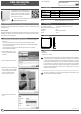
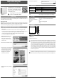
4. Wait until the device is ashing orange.
Press the button on the device briey,
as shown in the picture on the RMS
software. The LED ashes green,
when connection is succesful.
5. Enter the device name, channel and
group.
6. Finish conguration.
3 LED INDICATORS
Status LED Function Meaning
Connected Flashes green Status OK
Flashes red 2 times: no connection to the server
Not connected Flashes orange Device in pairing mode, push the button for integ-
ration into the software
4 ACCESSORIES
AC1321 Mounting kit with Allen key and mounting cone
5 TECHNICAL DATA
Power supply: 24 VDC ±10 % / <100 mA
Power supply requirements: 24 VDC ±10 % / >4 W / limited power source
Range of measurement / application: -40…70 °C
IP protection: IP65
Software: RMS Monitoring Software
Weight: 200 g
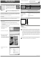
6 DIMENSIONS
7 DELIVERY PACKAGE
• Gateway
• Wall bracket
• Short instruction manual
This equipment has been tested and found to comply with the limits for a Class A digital de-
vice, pursuant to part 15 of the FCC Rules. These limits are designed to provide reasonable
protection against harmful interference when the equipment is operated in a commercial
environment. This equipment generates, uses, and can radiate radio frequency energy and,
if not installed and used in accordance with the instruction manual, may cause harmful
interference to radio communications. Operation of this equipment in a residential area is
likely to cause harmful interference in which case the user will be required to correct the
interference at his own expense.
Any changes or modications to this device not explicitly approved by manufacturer could
void your authority to operate this equipment.
105 mm
113 mm
38 mm