User Manual RTcom-Universal, Global Max and Outback Radio Modems Copyright Radio-Tech Limited 1998-2000
CONTENTS INTRODCUTION 3 Selecting the frequency of operation 5 R.
INTRODUCTION The RTcom-range of radio modem is intended as a direct replacement for cables over short, medium and long distance, serial data links. They are suitable for part of point-to-point, master to slave or scanning telemetry links, where the modem is either used on its own our in conjunction with existing cables. The modems also operate transparent to many industry standard network protocols, such as Modbus and Eiba Bus and can be used with many manufacturers PLC communication protocols.
In many countries it is quite legal to operate systems without need for operating licences. These countries include the United Kingdom, Australia, New Zealand, Korea, South Africa, Scandinavia and the majority of Europe. However, operation in these countries is normally subject to the equipment first being approved to a defined standard, such as the UK MPT1329 or the European ETS 300-220-1.
Frequency of operation Often there is not a choice over operating frequency. In most countries frequency allocations are very limited, by way of example in Europe there is only 433-435MHz UHF or 868-870MHz SHF. While the UK and many others offer VHF, UHF and SHF allocations. However other frequencies may be used subject to local government licence.
If there is doubt over the signal reaching the receiver a path survey should be conducted. The outback modem includes a test mode that places the modems transmitter into constant transmit mode. This permits the measurement of signal strength at the receiver. Normally our modems will work satisfactorily with a signal level below 1uV (-107dBm). INSTALLATION Power Supplies: As with any radio communications system, the RTcom modem should be connected to a clean and stable supply.
For battery powered operation in cold and damp climates the only reliable way to achieve long term operation is to use double IP65/7 enclosures, with both the outer and inner enclosure fitted with silica gel desiccant sachets. Please be aware that solar heating and wind chill can take the modem beyond its designed operating temperature range. Further, thermal cycling can encourage moisture ingress due to pressure changes. Whenever necessary please fit your enclosure with wind deflectors and/or sunshades.
Lightning Surge Protection: A direct lightning strike can never be totally protected against or predicted. Currents exceeding 10,000A can flow vaporising antenna, feeders, towers and other such structures. Lightning conductors will give a degree of protection to the building but not always to the electronic apparatus within. Generally the probability of a direct strike is very small, but a nearby strike with for example a 1km radius can be quite a regular occurrence in many locations.
Antenna Installation The type and location of the antenna used can have a profound effect on your overall system performance and its legality. In point to point links it is good practice to make efficient use of the radio spectrum by selecting an antenna that will project the R.F energy into the direction of desired operation and similarly at the receiver to collect transmissions only from the location of the transmitter.
Warning: The use of gain antenna in some countries is not permitted. Similarly where ERP (transmitted power limits) are imposed the actual transmitted power must not exceed the limit stated. This means that the transmitter output power, less any coaxial feeder losses, plus the antenna gain must not exceed the specified maximum ERP. Before installing your system please check! Antenna Types Antenna types fall into a number of categories.
Guide to your RTcom-Global & Max Modem Carrier Detect LED (Global only) Channel selection switch (Global Only, See Table) Mode Switch for RS232 / RS485 Modes Reset Button Status LED's Mode Switch for Data Rate and data format Links to select 2-4 wire RS485 12-24V dc supply RS422 & RS485 Interface RS232 interface 11
Guide to your RTcom-Outback Optional Location for Battery Configuration Mode Switch Solar/12-24V dc supply RS232 interface RS422 & RS485 Interface Links to select 2-4 wire RS485 Guide to your RTcom-Max (Please take care when opening cover) Radio Module mounted in cover Connections as per Global Modem 12
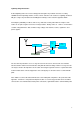
CONNECTIONS Data connections should always be made using screened cable. This will insure maximum rejection of interference from outside sources. Always use a common ground point. The RTcom Global, Eurpoa, MAX and Outback modems support RS232, RS422 and RS485 communications, both 2 and 4-wire. The RS232 port should be used for short cable runs of up to 10m and the RS422 and RS485 can be used for over 100m. The modems support various data rates from 1200 to 9600bps depending upon version.
Pin Number Designation WRT Modem 1 DCD 2 RX (data) 3 TX(data) 4 RTS 5 GND 6 B RX(-) 7 A RX(+) 8 +Vs 9 N/C 10 GND 11 Z = TX(-) 12 Y = TX(+) 13 +Vs 14 GND 15 + Vs Notes Optional not normally needed RS232 input data to modem RS232 output data from modem Optional not normally needed Ground RS485/RS422 " Supply 7.5 to 15V dc Ground RS485/RS422 " Optional supply connection.
On the Global and Max modems two dip switches are provided for the selection of the desired operating mode and two plug links are provided from the selection of 2 or 4 wire RS485 operation. A further DIP switch is provided on the Global modem for frequency Channel selection.
OPERATION The RTcom protocol permits 100% transparent operation and direct cable emulation. Simply what goes in comes out! R.F. packet framing, code balancing, encryption and preambles etc are taken care of automatically within the modem. Standard industrial communications protocols such as Modbus include a secure CRC 16 or 32 error check code on data transfers and will probably already be in use over your link, particularly if you are linking PLC's.
COMMISSIONING The data rate, parity and number of data bits are set using the dual in line switch located above. If a scanner is available the chosen channels and the adjacent channels should be scanned for activity. With frequency agile products such as the Max and Global a fee channel should be selected as far away as possible from the channel/s in use. The antenna should be positioned and one modem connected and set to test mode. The scanner should be used to measure the received signal strength.
system. This results in the messages becoming fragmented, thus confusing the modem into thinking the end of file has been detected. The other common problem, in particular with WindowsTM Hyper Terminal, is the way in which is deals with errors. Should an error occur it attempts to re-establish the link from both ends simultaneously, something of course that cannot be supported on a half duplex link.