
User manual

OPERATION
The RTcom™ protocol permits 100% transparent operation and direct cable emulation. Simply what goes
in comes out! R.F packet framing, code balancing, encryption and preambles etc are taken care of
automatically within the modem.
Standard industrial communications protocols such as MODBUS include a secure CRC 16 or 32 error
check code on data transfers and will probably already be in use over your link, particularly if you are
linking PLC’s. Rather than duplicate the CRC and risk increasing the overall bit error rate, the RTcom
protocol does not add any further error checking and subsequent time delay to your messages.
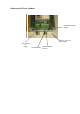
Status LED’s :
Status LED’s are provided to aid use. On the global and Universal, the top green LED indicates
power and the CPU status. If all is well, the LED will blink at a regular interval.
The centre amber LED is for received data communications (message received or sent to the data
terminal) by cable.
Finally, the bottom red LED indicates the transmission of data.
All LED’s Blink!:
If all LED’s should blink together, this indicates a data configuration error that is normally triggered by the
occurrence of a framing error. This is generally caused by the data rate and/or parity etc being incorrect at
the transmitting end. Manual intervention, i.e. changing the dip switches and/or the data terminal will be
required. NB. both ends of the link must share the same configuration.
Alternatively, this could also indicate incorrect wiring polarity of RS485 / RS422 connections.
Only after pressing and releasing the reset button will the new configuration become effective.