
User manual


Frequency of operation :
Often, there is not a choice over operating frequency. In most countries, frequency allocations are very
Limited. By way of example, in Europe there is only 433-435MHz UHF or 868-870MHz SHF, while the UK
and many others offer extra VHF, UHF and SHF allocations. However, other frequencies may be used
subject to local government licence.
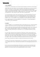
In order to generalise the choice of frequency, the decision should be based upon the distance of intended
operation, power supply constraints, data rate, duty cycle, attenuation, portability (antenna size) and the
presence of other users. The following table is produced to assist your choice.
VHF (10mW) UHF (10mW) UHF (500mW) SHF(5mW)
SHF
(500mW)*
Free Space Transmission
range
5-10km 3-5km 10-30km 100-200m 5-10km
Industrial installation
In large buildings
50-700m 50-500m 50m-1km 10-30m 30-100m
Penetration through concrete
walls
********** **** ****** * **
Ability to bend / defract around
Obstructions
********** ****** ****** ** **
Antenna size (dipole) 43cm 17cm 17cm 8cm 8cm
Potential users in adjacent
Channels
Message pagers
Radio Microphones
Radio
Amateur on
433MHz
Radio
Amateurs on
433MHz
Message
Pages on
458MHz and
TETRA on
410-430MHz
CT2
Mobile
telephones
CT2
Mobile
telephones
Transmission efficiency
For battery operation
********** **** **** *** ***
Relative cost
*** ***** ***** ******* ******
Fig. 3 : Frequency band table
RF Path Surveys :
The only certain way of determining the suitability of a communication channel is to conduct a radio path
survey and spectrum scan.
The spectrum scan is something normally conducted prior to ordering a system. Normally, this requires the
use of a good quality scanning receiver such as an ICOM 8500 and a broadband antenna. Failure to use a
quality scanner may result in signals being missed if channel resolution is too low and false signals being
detected if co-channel and image rejection is poor.
When scanning, both the desired and adjacent channels should be checked for signals. As transmissions
may be intermittent it is important to take time with the scan, stopping for as long as possible on each
channel and looking for at least 15 minutes on the final chosen band.
If there is any doubt over the signal reaching the receiver, a path survey should be conducted. Most
modems include a test mode that places the transmitter into constant transmit mode. This permits the
measurements of signal strength at the receiver. Normally, our modems will work with a signal
level below 1uV (-107dBm). However this may not leave adequate fade margin for the link. Normally
a signal better than -104 dBm should be used to provide reasonable margin.