2825 Ruckus Wireless 2825 Wireless Multimedia Router and 2111 Wireless Multimedia Adapter Part number: USM-2825-RKS1-121206-01 January 2007
Copyright © 2007 Ruckus Wireless, Inc. All rights reserved. January 2007. Trademarks Ruckus Wireless 2825, BeamFlex™, MediaFlex™, MediaFlex 2900 Multimedia Access Point, MediaFlex 2501 Multimedia Wireless Adapter, 2825 Wireless Multimedia Router, 2111 Wireless Multimedia Adapter, and 2211 Metro Broadband Gateway are trademarks of Ruckus Wireless Web Interface All other brands and product names are registered trademarks of their respective holders.
Contents Who Should Use this Guide . . . . . . . . . . . . . . . . . . . . . . . . . . . . . . . . . . . . . . . . . . . . . . . . . . . . . . . . What You’ll Find in this Guide . . . . . . . . . . . . . . . . . . . . . . . . . . . . . . . . . . . . . . . . . . . . . . . . . . . . . Typographic conventions . . . . . . . . . . . . . . . . . . . . . . . . . . . . . . . . . . . . . . . . . . . . . . . . . . . . . . . . . . System Requirements . . . . . . . . . . . . . . . . . . . . . . . . . . . . . . . . . .
Wireless Status . . . . . . . . . . . . . . . . . . . . . . . . . . . . . . . . . . . . . . . . . . . . . . . . . . . . . . . . . . . . . . . 40 Chapter 4 Maintenance . . . . . . . . . . . . . . . . . . . . . . . . . . . . . . . . . . . . . . . . . . . . . 43 Upgrading the Firmware. . . . . . . . . . . . . . . . . . . . . . . . . . . . . . . . . . . . . . . . . . . . . . . . . . . . . . . . . . . Performing a Firmware Upgrade by TFTP . . . . . . . . . . . . . . . . . . . . . . . . . . . . . . . . . . .
Who Should Use this Guide Preface This Ruckus Wireless 2825 Wireless Multimedia Router User’s Guide will help you understand the Ruckus Wireless 2825 Wireless Multimedia Router—how to install it, and configure it using the Ruckus Wireless Web Interface. Who Should Use this Guide This User’s Guide assumes that the reader has basic to intermediate computer and Internet skills. All the basic computer networking, Internet, and other information required to configure this device is provided herein.
System Requirements System Requirements The Ruckus Wireless 2825 Wireless Multimedia Router is compatible with most contemporary personal computers and operating systems that are configured for Internet and wireless networking. The VF2825 is accessed and configured via a Web browser interface. Any of the following Web browsers are supported: • Internet Explorer version 6.0 • Netscape version 8.1 • Firefox version 1.5.0.
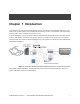
Chapter 1 Introduction Congratulations on your purchase of the Ruckus Wireless 2825 Wireless Multimedia Router (2825). The 2825 is a device that enables wireless multimedia networking for video, voice and data, without replacing existing routers, network adapters and media receivers. A typical installation consists of a Ruckus Wireless 2825 Wireless Multimedia Router connected to a DSL router or cable modem. The 2825 sends wireless signals to an adapter that is connected to a set top box.
MediaFlex™ MediaFlex™ MediaFlex™ is Ruckus Wireless, Inc.’s family of purpose-built, multimedia WiFi appliances that enable reliable wireless distribution of entertainment-quality, real-time media applications throughout the home. Media applications require consistent and uninterrupted bandwidth; however most wireless LANs (WLANs) cannot provide consistent service because of the variable nature of the wireless medium. Ruckus Wireless, Inc.
Key Features Multiple Concurrent Video Streams with Simultaneous Data Traffic • Delivers 15-20 Mbps of bandwidth at 99.9% availability throughout a typical 2500ft2 (300m2) home. • Supports one MPEG-4/WMV stream, one DVD-quality MPEG-2 streams, or one 10Mbps+ high definition video stream at 50ft (18m), with simultaneous data traffic.
Key Features This page is intentionally blank.
Chapter 2 Installation and Setup This chapter describes how to install your Ruckus Wireless 2825 Wireless Multimedia Router, and how to set up your PC to connect to the Ruckus Wireless Web Interface. Topics covered in this chapter include: Packing List. . . . . . . . . . . . . . . . . . . . . . . . . . . . . . . . . . . . . . . . . . . . . . . . . . . . . . . . . . . . . . . . . . . . . . . . . . . . 12 Ruckus Wireless 2825 Wireless Multimedia Router . . . . . . . . . . . . . . . . . . . . . . . . . . . . .
Packing List Packing List 1. Ruckus Wireless 2825 Wireless Multimedia Router 2. AC power adapter (Output DC 5-18V 1-2A) 3. Category 5 (CAT5) Ethernet Cable Ruckus Wireless 2825 Wireless Multimedia Router Front View Figure 2— “Front View of the Ruckus Wireless 2825 Wireless Multimedia Router” shows the front view of the 2825, with the LED indicators numbered. The numbers correspond to the labels describing LED behavior in Table 2— “LED Indicators and Meanings” on page 13.
LED Status Lights LED Status Lights Table 2— “LED Indicators and Meanings” describes the LED lights on the front of the 2825. Table 2—LED Indicators and Meanings Label 1 2 3 4 LED Dome Power WAN Connectivity Wireless Device Association USM-2825-RKS1-012907-01 Activity Description All LEDs On Green Solid The 2825 is booting. Counterclockwise flashing The 2825 is up. Green Flashing randomly The lit LEDs indicate which antennas are active. Green Power is supplied to the 2825.
LED Status Lights Table 2—LED Indicators and Meanings (Continued) Label LED 5 Activity Description Green Steady Good Signal Quality at the service provider WLAN interface. Displays the quality result of the adapter with the poorest reception, based on the RSSI at the service provider WLAN. Green Flashing Marginally Acceptable Signal Quality at the service provider WLAN interface. Displays the quality result of the adapter with the poorest reception, based on the RSSI at the service provider WLAN.
Placement Guidelines Table 3 describes the rear ports and Adapters. Table 3—Rear Ports Label Description 6 AC Power (Input 100-240V, 50/60HZ, 0.3A) 7 Five 10/100 Mbps Auto-sensing, autonegotiating RJ-45 network ports. The right-most port, labelled 'WAN', is to be connected to the broadband gateway. 8 Reset button. Used only if you need to reset the 2825 to its factory default settings. Insert the end of a paper clip or pin into the hole and hold it in for at least 8 seconds.
Configuring the Ruckus Wireless 2825 Wireless Multimedia Router Configuring the Ruckus Wireless 2825 Wireless Multimedia Router If it has not been already configured, you must configure your 2825 to work within your home network. Read the following section to understand how to configure it manually. NOTE – Depending on the pre-configurations of the 2825, the device behavior may be slightly different than what is described in this manual. Configuring an IP Address on Your Computer 1.
Configuring the Ruckus Wireless 2825 Wireless Multimedia Router Connecting the 2825 1. Connect the Ruckus MediaFlex Router's AC Power adapter to the VF2825 and plug the other end into a power outlet or to a surge protector that is plugged into a power outlet. Be sure the Power light on the VF2825 turns on. 2. The Power LED will turn green when you connect the power. 3. Connect the CAT5 Ethernet cable between the LAN port (any of the ports 1-4) on the 2825 and the Ethernet port on your PC.
Configuring the Ruckus Wireless 2825 Wireless Multimedia Router Figure 6—Login Window 7. The login screen appears, enter the username and password shown in Table 4. Click Login. The Status->Device window appears (Figure 7). Figure 7—Status->Device Window Configuring Wireless Settings 1. Choose Configuration->Wireless. The window of Figure 8 appears.
Troubleshooting Figure 8—Configure->Wireless Settings (Common) 2. For the Wireless Mode, choose Auto-select. 3. For the Channel, choose SmartSelect.. 4. When you are finished, click Update Settings. 5. Refer to the information in the help button for any explanations you may need. Troubleshooting If you can’t connect to the 2825, follow this startup sequence: 1. Unplug the 2825’s power adapter. 2. Plug in the 2825’s power adapter. 3. Connect the WAN port of the 2825 to your DSL modem or gateway. 4.
Troubleshooting 13. Make sure the Power LED is lit. If it is not lit, make sure that the power cord is properly connected to the 2825, and that the AC power adapter is properly connected to a functioning power outlet. If the problem persists, you have a hardware problem and should contact technical support. 14. Make sure your WAN Connectivity LED is lit. Make sure that the Ethernet cable connections are secure at the 2825 and your computer.
Chapter 3 Using the Ruckus Wireless Web Interface This chapter describes the tasks you need to do to customize the 2825 to run on your wireless network. Topics covered in this chapter include: • Wireless Settings Worksheet. . . . . . . . . . . . . . . . . . . . . . . . . . . . . . . . . . . . . . . . . . . . . . . . . . . . . . . . . . . . 22 • 2825 Settings Worksheet. . . . . . . . . . . . . . . . . . . . . . . . . . . . . . . . . . . . . . . . . . . . . . . . . . . . . . . . . . . . . . .
Wireless Settings Worksheet Wireless Settings Worksheet The 2825 is equipped with Virtual Access Point (VAP) whereby there are two wireless networks. One network is for the home user and another network for the service provider. Typically, the home network is used for a PC to access the Internet. The Service Provider network is typically used for video streaming.
2825 Settings Worksheet Table 6 is the Wireless Network Settings Worksheet for the service provider user. Table 6—Wireless Network Settings Worksheet—Service Provider User Item Description and Your Network Setting 2825 SSID The SSID for the service provider. This is typically used for streaming IPTV video content.
2825 Settings Worksheet Table 7—2825 Default and User Settings Worksheet (Continued) Item Default Setting Service Provider User Name super Your Setting _______________________________ Service Provider Password sp-admin _______________________________ Internet Access Type DHCP Client Enabled (can be set to static or PPPoE) Local Network Configuration _______________________________ DHCP Server Enabled _______________________________ Default IP Address (LAN ports) 192.168.1.
Ruckus Wireless Web Interface Menus Ruckus Wireless Web Interface Menus The Ruckus Wireless Web Interface menus are located on the left-hand navigation pane. To select a particular menu, simply click on the menu link. Common Buttons The Ruckus Wireless Web Interface screens contain the following menu buttons (Table 8): Table 8—Wireless Web Interface Menu Buttons Button Action Logout Logs out from the current session. Restore Previous Settings Restores the original configuration.
Configuring the 2825 Figure 9—Device Configuration 3. Enter your configuration changes in the appropriate fields. 4. Click Update Settings to save your settings. Customizing the System Configuration It is recommended that you customize the username and password so that you can control who can gain administrative access to the 2825. You may also wish to change the default IP address if it conflicts with another device in your wireless network. Refer to Table 7 for details on each field.
Configuring the 2825 Internet Configuration To define how the 2825 is configured to the Internet, use the Configuration->Internet menu. 1. Connect to the 2825 by following the instructions in "Configuring the Ruckus Wireless 2825 Wireless Multimedia Router" on page 16. 2. Choose Configuration->Internet. The window of Figure 10 appears. Figure 10—Internet Configuration Table 9 shows the Internet Configuration Parameters.
Configuring the 2825 After connecting to the 2825 Wireless Multimedia Router, choose Configuration->Wireless. If you logged on as a home user, the window of Figure 11 appears. If you logged on as a service provider user, the window of Figure 12 appears. Figure 11—Configure Wireless—Coimmon—Home User Figure 12—Configure Wireless—Common—Service Provider User The parameters are the same, except the service provider user window shows more Wi-Fi HotSpots.
Configuring the 2825 3. Choose the Wireless Mode, Channel, and Country code as described in Table 10. Table 10—Wireless Interface Configuration Field Description Wireless mode The wireless mode options are: • • • Auto-Select: - Allows both 802.11g- and 802.11b-compliant devices to join the network. This is the default setting. 2.4 GHz 54 Mbps (802.11g only): Allows only the 802.11g-compliant devices to join the network 2.4GHz 11Mbps (802.11b only): - Allows only 802.
Configuring the 2825 Table 11—Advanced Wireless Settings Field Description Data Rate Specifies the rate of data transmission. Select the desired rate from the drop-down menu. Selecting Best adapts the rate to the best available. The default value is Best. The data rates that appear in the Data Rate drop-down menu are dependent on the Wireless Mode specified. Transmit Power Specifies the maximum transmit power level relative to the calibrated power.
Configuring the 2825 Table 12—Security Disabled Parameters (Continued) Field Description Encryption Method Disabled: No encryption is enabled in this mode. WEP: See WEP Settings below for details. WPA-PSK: See WPA Settings below for details. This is recommended for best privacy protection. Threshold Settings Click on the button to access the wireless network threshold settings. Changing these settings is not recommended and may negatively impact performance.
Configuring the 2825 Table 13—Threshold Settings Parameters Field Description DTIM Interval The value indicates the interval of the Delivery Traffic Indication Message (DTIM). This is a countdown field that Access Point (AP) informs its clients of the next window for listening to broadcast or multicast messages. The default value is 1. Fragment Threshold This value indicates the maximum length of a packet before data is fragmented into multiple packets.
Configuring the 2825 Configuring WEP To configure WEP for a Wi-Fi HotSpot: 1. Choose Configuration -> Wireless link in the left-hand navigation pane of Figure 14. 2. Click the HotSpot you want to configure. 3. Select WEP in the Encryption Method drop-down menu. The WEP Configuration window of Figure 15 appears for the tab you selected. Figure 15—WEP Configuration Table 14 describes the WEP configuration settings.
Configuring the 2825 Table 14—WEP Configuration Settings Field Description Authentication Mode Choices are: Encryption Strength • • • Open: No security measure is enforced. Shared Key: The selected Default Shared Key is used. Auto: Automatically-selected authentication mode. oices are: • 64 bit: Specify the key with 10 hexadecimal digits or 5 ASCII characters. 128 bit: Specify the key with 26 hexadecimal digits or 13 ASCII characters.
Configuring the 2825 Figure 16—WPA-PSK Wireless Settings 1. Click the Configuration -> Wireless link in the left-hand navigation pane (Figure 11). 2. Select WPA-PSK in the Encryption Method drop-down menu. Table 15 explains the WPA Configuration parameters Table 15—WPA Algorithm Field Description WPA Version Choices are WPA, WPA2 or WPA Auto. When WPA-Auto is selected, the wireless client decides the version of WPA will be used. WPA is the recommended default for best compatibility.
Configuring the 2825 Table 15—WPA Algorithm (Continued) WPA Algorithm When Auto is selected, the wireless client decides whether TKIP or AES will be used. AES is the strongest encryption and requires additional hardware support on wireless devices.You should consult the documentation of your wireless client devices.Auto is an advanced option and some wireless clients may fail to associate. Passphrase Enter any combination of printable characters. The Passphrase must be between 8 and 32 characters long.
Viewing Status Information Viewing Status Information There are four status information windows. These are Device Status, Internet Status, Local Network Status and Wireless Status. Device Status The Status page shows current status and configuration information about the Ruckus Wireless Router or Adapter. Figure 17 shows the Device Status window. You can bring up the window by choosing Status->Device. Figure 17—Device Status Window Table 16 explains the Device Status Parameters.
Viewing Status Information Internet Status Figure 18 shows the Internet Status window. You can bring up the window by choosing Status->Internet. Figure 18—Internet Status Window The Internet Status window shows the values and status of the various parameters that were configured in the Configuration section. You can also renew and release DHCP request to the DHCP servers located on the network. If you enable auto update, the information will be continuously updated on the display.
Viewing Status Information NOTE – When Internet connection type is either DHCP or PPPoE, if the 2825 does not receive the dynamic IP address from DHCP server or PPPoE server, the default IP address for WAN port will be 192.168.0.1 Local Services Status Figure 19 shows the Local Services Status Window. You can bring up the window by choosing Status->Local Services. Figure 19—Local Network Status Window The local services status window shows automatically discovered devices you can manage.
Viewing Status Information Wireless Status Figure 20 shows the Wireless Status Window.You can bring up the window by choosing Status->Wireless. Note that the common settings are displayed. Figure 20—Wireless Status—Common To view the wireless status of a HotSpot, click that tab (Figure 21). Figure 21—Wireless Status—HotSpot Table 18 shows the Wireless Information Window parameters.
Viewing Status Information Table 18—Wireless Status Window Parameters Field Description Wireless Mode The wireless mode, such as 2.4 GHz (802.11b/g) Channel The wireless channel number. Country code The country in which the 2825 is operating.The country code will automatically select the Channels available for that country. SSID The SSID (Service Set Identifier) is the name of the wireless network (either the home wireless or the service provider wireless domain).
Viewing Status Information 42 Ruckus Wireless 2825 Wireless Multimedia Router USM-2825-RKS1-012907-01
Chapter 4 Maintenance This chapter shows you how to perform maintenance functions—to upgrade the firmware of the 2825 and to take a system support snapshot. Topics covered in this chapter include: • Upgrading the Firmware. . . . . . . . . . . . . . . . . . . . . . . . . . . . . . . . . . . . . . . . . . . . . . . . . . . . . . . . . . . . . . . 44 • Rebooting the System . . . . . . . . . . . . . . . . . . . . . . . . . . . . . . . . . . . . . . . . . . . . . . . . . . . . . . . . . . . . . . . . .
Upgrading the Firmware Upgrading the Firmware This menu provides a utility for upgrading the 2825’s firmware. A firmware upgrade may be necessary or desirable to add new features, important fixes or enhancements to the 2825. The Image Control File contains information on both the image and the firmware server. Image information includes the file size and file name.
Upgrading the Firmware Figure 23—Download Started Firmware Upgrade by FTP 1. If you want to perform the download using FTP, then check FTP as the upgrade method after choosing Maintenance->Upgrade. The window of Figure 24 appears. Figure 24—Maintenance->Upgrade—FTP 2. Enter the IP Address or the host name of the FTP server and the image control file name. 3. If you want to enable Auto Upgrade, click Enabled, and specify the interval to check for upgrades.
Rebooting the System NOTE – When entering the server name for firmware upgrade, make sure the Fully Qualified Domain Name (FQDN) is entered (for example, abc.ruckuswireless.com). Performing a Firmware Upgrade Using HTTP 1. If you want to perform the download using HTTP, then check Web as the upgrade method after choosing Maintenance->Upgrade. The window of Figure 25 appears. Figure 25—Maintenance->Upgrade—Web/HTTP 2. Enter the URL of the web server and the image control file name. 3.
Rebooting the System • Any configuration changes made before the Reboot will be lost if they are not saved by clicking Update Settings.The Reset to Factory Settings button restarts the system with the factory default configurations. All previous configurations will be lost. 1. To reboot for either type, click Maintenance->Reboot/Reset from any window. The window of Figure 26 appears. Figure 26—Reboot Menu 2. Click the reboot option you want.
Taking a System Support Snapshot Figure 28—Reboot Done Taking a System Support Snapshot NOTE – This menu is only available when you are logged in as a service provider. The Support menu enables you to take a system snapshot for further analysis and troubleshooting. The system snapshot can be sent and saved to a TFTP or FTP server for analysis by a technical support engineer. 1. To view the support menu, choose Maintenance->Support Info from any window. The window of Figure 29 appears.
Taking a System Support Snapshot Figure 29—Maintenance Support Info Window You can upload the information to a remote server using FTP or TFTP, or alternatively, save it to your local computer. 2. To save to your local computer, you need to right-click on the link that appears and save. 3. Navigate to the folder where you want the file saved and click Save. 4. To upload to a remote server using either FTP or TFTP, enter the filename, username and password of the FTP server and click Update Now.
Administrator Information Administrator Information NOTE – This menu is available only when you are logged in as a service provider. Management Information Figure 30 shows the Administrator Management Window. 1. Open this window by choosing Administrator->Management. Figure 30—Administrator Management Window Table 19 shows the Administrator Management Window Parameters.
Administrator Information Table 19—Administrator Management Window Parameters (Continued) Field Description SSH Port Specifies the port number for Telnet access. The default port number is 23. HTTP Access? This allows you to enable or disable HTTP (Web) access to the Router or Adapter. HTTPS Access? This allows you to enable or disable HTTPS (Secure Web) access to the Router or Adapter. HTTPS Port Specify the port number for HTTPS access. The default port number is 80.
Administrator Information Figure 31—Administrator Diagnostics Window 2. To use the ping command, enter the IP address you wish to ping and click Run test. The results appear in the Ping results window. 3. To use the traceroute command, enter the IP address you wish to trace and click Run test. The results appear in the Traceroute results window. NOTE – It may take some time before the results are displayed.
Administrator Information Administrator Log The current log screen shows the log messages kept by the Ruckus Wireless Router since it was last rebooted. The log has limited size: the oldest messages are replaced as new messages arrive. It also sends the messages to a server (the Syslog server) that you designate. To configure the administrator log: 1. Choose Administrator->Log. The window of Figure 32 opens. Figure 32—Administrator Log Window 2.
Administrator Information 54 Ruckus Wireless 2825 Wireless Multimedia Router USM-2825-RKS1-012907-01
Chapter 5 Setting Up the Ruckus 2111 Multimedia Wireless Adapter This chapter shows you how to set up the Ruckus 2111 Multimedia Wireless Adapter with the 2825 Wireless Multimedia Router. Topics covered in this chapter include • Packing List . . . . . . . . . . . . . . . . . . . . . . . . . . . . . . . . . . . . . . . . . . . . . . . . . . . . . . . . . . . . . . . . . . . . . . . . . 56 • Placing the 2111 Into Operation . . . . . . . . . . . . . . . . . . . . . . . . . . . . . . . . . . . . . . . . . .
Packing List Packing List Each 2111 is supplied with the following: • Ruckus 2111 Multimedia Wireless Adapter • AC power adapter • Category 5 (CAT5) Ethernet cable • Ruckus 2111 Multimedia Wireless Adapter Quick Setup Guide Placing the 2111 Into Operation The 2111 is the Wireless Multimedia Adapter connecting to the set top box or other media receivers while communicating wirelessly to the 2825 Wireless Multimedia Router.
Verifying Proper Provisioning Dome Signal Quality Power WAN Connectivity Wireless Device Association Figure 33—LEDs 12. Make sure you are using the power adapter supplied by Ruckus Wireless. 13. Make sure the Power LED is lit. If it is not lit, make sure that the power cord is properly connected to the 2111 Adapter, and that the power supply adapter is properly connected to a functioning power outlet. If the error persists, you have a hardware problem and should contact technical support. 14.
Verifying Proper Provisioning 7. Click OK to exit the TCP/IP Properties window. 8. Click OK to exit the Local Area Connection Properties window. Connecting and Configuring Your Ruckus 2111 Multimedia Wireless Adapter The following steps will guide you to set up and gain administrative access to your Ruckus 2111. 1. Move the Ruckus 2111 next to your computer. 2.
Chapter 6 Auto Provisioning This chapter shows you how to perform auto provisioning of the 2825 Wireless Multimedia Router. Topics covered in this chapter include: • What is Auto Provisioning? . . . . . . . . . . . . . . . . . . . . . . . . . . . . . . . . . . . . . . . . . . . . . . . . . . . . . . . . . . . . 60 • Performing Auto Provisioning . . . . . . . . . . . . . . . . . . . . . . . . . . . . . . . . . . . . . . . . . . . . . . . . . . . . . . . . . .
What is Auto Provisioning? What is Auto Provisioning? Using auto provisioning, either a service provider or home user can synchronize configuration parameters between the 2111 and the 2825. In order for the adapter to communicate with the AP, the 2111 must have the same wireless settings (such as SSID, security mode, and passphrase) as the 2825. With auto provisioning, the adapter can obtain these settings without the need to use a PC for configurtation. The auto provisioning method is very simple.
Performing Auto Provisioning Table 20— 2825 Parameters Included in Auto Provisioning Parameter Description SSID Configured Service Set Identifier Encryption mode Configured encryption mode status Cipher Configured security encryption cipher Authentication type Configured authentication method Passphrase Configured Pre-Shared Passphrase WEP keys Configured WEP Pre-Shared Keys Default key Configured WEP default key number 2825 Parameters Not Included in Auto Provisioning The following less co
Performing Auto Provisioning 62 Ruckus Wiireless 2825 Wireless Multimedia Router USM-2825-RKS1-012907-01
Appendix A: Technical Specifications Physical Characteristics VF2825: 5V-18V 10W External power adapter: Power requirements Unifive Technology Co LTD, Model US300520, Input 100-240V AC, Output 5V DC 2A, UL Listed DVE, Model DSA-031F-12 UK 12, Input 100-240V AC, Output 12V DC 1A, TUV Certified DVE, Model DSA-031F-12 EU 12, Input 100-240V AC, Output 12V DC 1A, TUV Certified Physical size 5.72 x 4.92 x 2.9 in (145 x 125 x 74 mm.) Weight 0.53 lbs (0.
Traffic Management and QoS 2-3 simultaneous MPEG-4/WMV streams, or 1-2 DVD-quality MPEG-2 streams, or a single 10Mbps+ high definition stream at 50ft (18m) with simultaneous background traffic Number of simultaneous video streams Traffic Management and QoS Classes of service Voice, Video, Best Effort and Background Number of hardware queues 4 Number of software queues 4 Management Configuration and monitoring interface Login Statistics Ruckus Wireless Web User Interface (WebUI), Telnet, SNMP Home