O W N E R ’S O P E R A T I N G M A N U A L VX-2cx VX-2dcx Digital Light ProcessingTM Projector and DHD Controller
TWO YEAR LIMITED WARRANTY For Projectors, Video Processors and Controllers Congratulations on your purchase of a Runco video product and welcome to the Runco family! We believe Runco produces “The World’s Finest Home Theater Products.” With proper installation, setup and care, you should enjoy many years of unparalleled video performance. This is a LIMITED WARRANTY as defined in the Magnuson-Moss Warranty Act. Please read it carefully and retain it with your other important documents.
EFFECTIVE WARRANTY DATE: This warranty begins on the effective date of delivery to the end user. For your convenience, keep the original bill of sale as evidence of the purchase date. IMPORTANT – WARRANTY REGISTRATION: Y Please fill out and mail your warranty registration card. It is imperative that Runco knows how to reach you promptly if we should discover a safety problem or product update for which you must be notified.
ADDITIONAL INFORMATION: To locate the name and address of the nearest Runco Authorized Service Center, or for additional information about this Limited Warranty, please call or write: EL IM IN A R Y RUNCO INTERNATIONAL, INC.
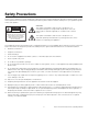
Safety Precautions Thank you for your purchase of this quality Runco video projector! It has been designed to provide you with the quality of video that is expected in a home theater. For the best performance, please read this manual carefully as it is your guide through the menus and operation. This symbol is intended to alert the user to the presence of important operating and maintenance (servicing) instructions in the literature accompanying the appliance.
1 Table of Contents TWO YEAR LIMITED WARRANTY ................................................................................. iii Safety Precautions ......................................................................................................... vi 1. Introduction ...............................................................................................................1 About This Manual .......................................................................................................
Table of Contents Installing the Optional CineWide Lens .........................................................................25 Mounting the VX-2 .....................................................................................................26 Floor Mounting (Upright) .......................................................................................26 Ceiling Mounting (Inverted)....................................................................................
Table of Contents 6. Serial Communications ..........................................................................................61 RS-232 Connection and Port Configuration ...............................................................61 Serial Command Syntax .............................................................................................61 7. Specifications ..........................................................................................................67 VX-2 Specifications ...
Table of Contents PR EL IM IN A R Y Notes: x Runco VX-2cx/VX-2dcx Owner’s Operating Manual
1 List of Figures 2-1. VX-2cx Front/Bottom/Side View ...................................................................................5 2-2. VX-2dcx Front/Bottom/Side/Top View..........................................................................6 2-3. VX-2 Rear Panel ...........................................................................................................7 2-4. DHD Controller Front Panel ..........................................................................................
List of Figures Notes: xii Runco VX-2cx/VX-2dcx Owner’s Operating Manual
1. Introduction This Owner’s Manual describes how to install, set up and operate the Runco VX-2cx or VX-2dcx DLP Projector and DHD Controller. 1.1 About This Manual Y Throughout this manual, the Runco VX-2cx or VX-2dcx DLP Projector and DHD Controller are referred to collectively as the “VX-2.” The information in this manual applies to both projectors except where otherwise indicated. EL IM IN A R Runco has prepared this manual to help home theater installers and end users get the most out of the VX-2.
Introduction Graphic Conventions: These symbols appear in numerous places throughout the manual, to emphasize points that you must keep in mind to avoid problems with your equipment or injury: Note NOTES emphasize text with unusual importance or special significance. They also provide supplemental information. Caution CAUTIONS alert users that a given action or omitted action can degrade performance or cause a malfunction.
Introduction Runco steps into the future once again with the Video Xtreme™ VX-2cx and VX-2dcx (“VX-2“) Digital Light Processing (DLP™) Projectors, among the world’s first THX® Certified, high-definition home theater projectors. Note THX recommends the use of 720p source material for optimal performance with this product.
Introduction Key Features and Benefits ➤ The VX-2 offers these key features and benefits: • Native Resolution: 1280 x 720 (16:9 Native Aspect Ratio) • Three-chip Digital Light Processing (DLP™) system • Two DVI Inputs (on DHD Controller) with High-bandwidth Digital Content Protection (HDCP) • HDTV Compatible • CinOptx™ Proteus (VX-2cx) or Telesto (VX-2dcx) lens options for stunning sharpness and throw distance flexibility Your VX-2 is shipped with the following items.
2. Controls and Functions 2.1 VX-2 at a Glance Figure 2-1 and Figure 2-2 show the key VX-2 components. 2 3 5 PR EL IM IN A R Y 1 4 Figure 2-1. VX-2cx Front/Bottom/Side View 1. INTAKE VENT 2. LENS 3. RUNCO LOGO The logo can be rotated to match the projector orientation: inverted (ceiling-mounted) or upright. To rotate the logo, grip it at the sides, pull it away from the projector and rotate it 180 degrees. 4. EXHAUST VENT 5. CABLE OPENING Pass cables through this opening.
Controls and Functions 2 3 EL IM IN A R Y 1 5 4 PR 6 7 Figure 2-2. VX-2dcx Front/Bottom/Side/Top View 1. INTAKE VENT 2. LENS 3. RUNCO LOGO The logo can be rotated to match the projector orientation: inverted (ceiling-mounted) or upright. To rotate the logo, grip it at the sides, pull it away from the projector and rotate it 180 degrees. 4.
Controls and Functions 5. CABLE OPENING Pass cables through this opening. 6. VERTICAL LENS SHIFT ADJUSTMENT 7. HORIZONTAL LENS SHIFT ADJUSTMENT 2.2 VX-2 Rear Panel Figure 2-3 shows the VX-2 rear panel. 2 3 4 5 PR EL IM IN A R Y 1 ON / OFF AC IN 120V 60HZ VX-2 DIGITAL PROJECTOR 6 7 8 9 10 11 12 Figure 2-3. VX-2 Rear Panel 1. VACUUM FLUORESCENT DISPLAY Displays currently-selected menu. If no menu is selected, “Runco VX-2” appears here. 2. PROGRAM PORT For service use only. 3.
Controls and Functions 6. LAMP COVER Remove this cover to access the lamp compartment. 7. UP BUTTON Used to move the menu cursor up in the VX-2 menu system. 8. LEFT BUTTON Used to move the menu cursor left in the VX-2 menu system. 9. DOWN BUTTON Used to move the menu cursor down in the VX-2 menu system. Y 10. ENTER BUTTON When an item is highlighted on the On-Screen Display, the ENTER button selects the item. EL IM IN A R 11. RIGHT BUTTON Used to move the menu cursor right in the VX-2 menu system. 12.
Controls and Functions 2.3 DHD Controller Front Panel 1 2 EL IM IN A R Y Figure 2-4 shows the controls and indicators on the DHD Controller front panel; the paragraphs that follow describe them. 3 4 5 6 7 8 Figure 2-4. DHD Controller Front Panel 1. RUNCO ICON Lights red to indicate that the DHD Controller is in standby mode; lights blue to indicate that the unit is on. 2. POWER BUTTON Press once to toggle from standby mode to on mode. Press it again to return to standby mode.
Controls and Functions 7. ENTER BUTTON When an item is highlighted on the On-Screen Display, the ENTER button selects the item. 8. DOWN BUTTON Use to direct select aspect ratios or move the menu cursor down in the On-Screen Display. When no menu is present on-screen, this button toggles you through the different aspect ratios, in this order: Virtualwide 2.35 - Cinema - VirtualWide - Letterbox - Standard (4:3) - Anamorphic EL IM IN A R Y 9.
Controls and Functions 2.4 DHD Controller Rear Panel Figure 2-5 shows the rear connector panel on the DHD Controller. 8 4 10 SYSTEM CONTROL INTERFACE R/Pr G/Y B/Pb RISK OF ELECTRIC SHOCK DO NOT OPEN H V OUTPUTS HD2 B/Pb Video Processor / Controller G/Y B/Pb H V EL IM IN A R R/Pr SDI V 1 H/V DVI Out 2 DVI 1 DVI 2 Option 3 Pb Pr Component Video 5 2 Y 1 H CAUTION: TO REDUCE THE RISK OF ELECTRIC SHOCK, DO NOT REMOVE COVER. NO USERSERVICEABLE PARTS INSIDE.
Controls and Functions 6. COMPOSITE VIDEO INPUT Standard composite video input for connecting a VCR, laser disc player or other composite video source. 7. S-VIDEO 1 / S-VIDEO 2 Two, standard S-Video inputs for connecting a DVD player, satellite receiver or Super VHS (S-VHS) VCR. 8. 12-VOLT (750 mA) TRIGGER OUTPUTS Connection for up to three (3), 12-volt trigger-controlled devices. These can be retractable screens, screen masks or the Runco CineWide with AutoScope system. Y 9.
Controls and Functions Figure 2-6 shows the VX-2 remote control, and the paragraphs that follow describe its functionality. 2 Y 1 4 EL IM IN A R 3 6 5 7 10 11 8 13 PR 9 12 Figure 2-6. VX-2 Remote Control Runco VX-2cx/VX-2dcx Owner’s Operating Manual 13 2.
Controls and Functions 1. IR OUTPUT INDICATOR Lights when a button is pressed to indicate that an IR signal is being transmitted. 2. ON / OFF Press to turn the projector on or off. 3. ENTER Press to select a highlighted menu item or confirm a changed setting. 4. Cursor Buttons ( , , , ) Use these buttons to select items or settings, adjust settings or switch display patterns.
Controls and Functions 9. Aspect Ratio Selection Buttons Use the red buttons to select an aspect ratio directly or to enter numeric characters, as follows: ANA (Anamorphic) (3) For viewing 16:9 DVDs or HDTV programs in their native aspect ratio. 4X3 (Standard 4:3) (6) Scales the input signal to fit 4:3 display mode in the center of the screen. Y LETBOX (Letterbox) (9) For viewing LaserDisc movies or non-anamorphic DVDs on a 4:3 screen.
Controls and Functions PR EL IM IN A R Y Notes: 16 Runco VX-2cx/VX-2dcx Owner’s Operating Manual
3. Installation 3.1 Remote Control EL IM IN A R Y To install batteries in the remote control, press up on the battery cover retainer clip and lift off the cover. Install the two AAA batteries with the correct polarity and then replace the cover. • Make sure that the battery polarities are correct when installing the batteries. Notes on Batteries • Do not mix an old battery with a new one or different types of batteries.
Installation 3.2 Quick Setup Table 3-1 gives a quick overview of the VX-2 installation process. The sections following this one provide detailed instructions. Note Installation should be performed by a qualified custom video installation specialist. Y Table 3-1. Installation Overview Procedure PR EL IM IN A R Step For Details, Refer to page...
Installation Proper installation of your projector will ensure the quality of your display. Whether you are installing a projector temporarily or permanently, you should take the following into account to ensure your projector performs optimally. 3.3 Installation Considerations Choose the installation type that best suits your needs: front or rear screen, floor mount or inverted mount. Table 3-2 compares these various installation methods.
Installation Throw Distance ➤ Throw distance is the distance measured from the front of the projector to the screen. This is an important calculation in any projector installation as it determines whether or not you have enough room to install your projector with a desired screen size and if your image will be the right size for your screen. You can quickly estimate the throw distance by taking the width of the screen and multiplying it by the lens throw ratio; see Figure 3-1.
Installation Table 3-3. VX-2cx Lens Options and Throw Ratios (continued) Throw Ratio Lens Option with Primary (Note 2) Lens Only Throw Range in inches, with 96x54-inch (1.78:1) Screen Minimum Throw Range in Throw Ratio inches, with with Primary 126.9x54-inch (2.35:1) Lens and Screen Anamorphic Lens Maximum Minimum Maximum Proteus E 2.42 - 3.57 232.32 342.72 1.84 - 2.64 233.50 335.02 Proteus F 3.63 - 5.72 348.48 549.12 2.75 - 4.26 348.98 540.59 Y Notes: 1.
Installation Vertical and Horizontal ➤ Position Proper placement of the projector relative to the screen will yield a rectangular, perfectly-centered image that completely fills the screen. Ideally, the projector should be positioned perpendicular to the screen and in such a way that the lens center and screen center are aligned with each other, as shown in Figure 3-2.
Installation 150% Width Lens Shift (1.5 x W) 100% Width Lens Shift (1.0 x W) 50% Width Lens Shift (0.5 x W) Screen Center EL IM IN A R Screen Width (W) Y 0% PR Note: This is a general example of lens shift. Lenses vary in their shift capabilities. No particular lens or projector is used in this example. Figure 3-4. Horizontal Lens Shift (Example Only) Vertical Lens Shift - VX-2cx: The VX-2cx zoom lenses (Proteus B through F) provide up to 80% of downward vertical lens shift.
Installation Vertical and Horizontal Lens Shift - VX-2dcx: Table 3-5 lists the lens shift limits for each available VX-2dcx lens, as percentages and absolute measurements with a 100 x 56 inch (1.78:1) screen. Table 3-5.
Installation In rear screen applications where space behind the projector is limited, a mirror may be used to fold the optical path, as shown in Figure 3-5. The position of the projector and mirror must be accurately set. If you are considering this type of installation, contact your dealer for assistance. Folded Optics Screen Figure 3-5.
Installation 3.5 Mounting the VX-2 There are several methods for mounting the projector. Depending on your chosen installation, one method may be more suitable than another. In typical front and rear screen installations, the projector can be mounted to a secure and level surface such as a table or cart. Carts are useful when moving a projector during a presentation or from site to site. If possible, lock the wheels when it’s in position to prevent it from being moved during a presentation.
Installation Proceed as follows to connect the DHD Controller to the VX-2, your video sources, external controller(s) – if present – and AC power. When connecting your equipment: • Turn off all equipment before making any connections. 3.6 Connections to the VX-2 and DHD Controller • Use the correct signal cables for each source. • Ensure that the cables are securely connected. Tighten the thumbscrews on connectors that have them.
Installation Connecting Source ➤ Components to the DHD Controller Connect your video sources to the DHD Controller as shown and described in the sections that follow. DVI Connections: See Figure 3-7. Use the DVI inputs whenever possible. This ensures the highest video quality because the signal is carried in the digital domain throughout the entire signal path, from source component output into the projector.
Installation Digital (DTV) RGB or Component Video Connections: See Figure 3-8. R/Pr G/Y INPUTS B/Pb H V TRIGGERS HD1 1 2 3 HD2 R/Pr G/Y B/Pb H V DVI 1 Pb Pr Y Component Video Video S-Video 2 EL IM IN A R DVI 2 Y S-Video 1 Horiz Vert PR Red/Pr Green/Y Blue/Pb DTV or Progressive Component (YPbPr) Source Figure 3-8.
Installation Analog (Computer) RGB Connections: See Figure 3-9. R/Pr G/Y INPUTS B/Pb H V TRIGGERS HD1 1 2 3 HD2 G/Y R/Pr B/Pb H V S-Video 1 Pb DVI 2 Y Pr Component Video Video S-Video 2 EL IM IN A R Y DVI 1 PR Red Green Blue Horiz Vert Personal Computer Figure 3-9.
Installation Composite/S-Video/Component Video Connections: See Figure 3-10. R/Pr G/Y INPUTS B/Pb H V TRIGGERS HD1 1 2 3 HD2 R/Pr G/Y B/Pb H V S-Video 1 DVI 2 Pb Y Pr Component Video Video S-Video 2 EL IM IN A R Y DVI 1 Pr Y PR Pb DVD Player, VCR, Satellite Receiver, Laser Disc etc. Figure 3-10.
Installation RS-232 Controller ➤ Connection Use a standard, 9-pin RS-232 cable to connect a PC or home theater control/automation system (if present) to the RS-232 Control port on the DHD Controller; see Figure 3-11. For more information about using this connection, refer to Serial Communications on page 61.
Installation If your home theater contains a retractable screen, screen mask or other 12-volt trigger-activated equipment, connect it to a 12-volt trigger output as shown in Figure 3-13. TRIGGERS 2 1 Pr Component Video IR S-Video 1 Y Video S-Video 2 RS-232 Out RS-232 Control to 12-Volt trigger-activated equipment EL IM IN A R 3.5-mm mini plug Y Pb 3 Sleeve = Ground Tip = +12V Figure 3-13.
Installation PR EL IM IN A R Y Notes: 34 Runco VX-2cx/VX-2dcx Owner’s Operating Manual
4. Operation 4.1 Turning on the Power 1. Turn on your source components. 2. Turn on the main power switch at the rear of the projector. 3. Turn on the main power switch at the rear of the DHD Controller. Y 4. If this is an AutoScope-equipped projector, turn on the main power switch at the rear of the AutoScope lens motor. The lens motor power switch is located next to the AC input. EL IM IN A R 5.
Operation 4.3 Lens Adjustments To access the motorized lens controls, select Display Device from the Service Menu, then select Lens from the Display Device menu. The Lens menu gives you a great deal of control over the picture size, position and focus: Focus ➤ To focus the projected image, use the cursor buttons to highlight “In” or “Out.” Then, press and hold the ENTER button. Zoom ➤ To make the picture smaller (zoom out), use the cursor buttons to highlight the minus sign (-).
Operation Press the MENU button on either the remote control or the DHD Controller front panel to display the Main Menu. To select a menu item, use the and buttons on either the remote control or the DHD Controller front panel to highlight it. Press ENTER to confirm your selection. PR EL IM IN A R Y The VX-2 OSD menus are arranged hierarchically, as shown in Figure 4-2. Runco VX-2cx/VX-2dcx Owner’s Operating Manual 37 4.
Operation Picture Input Position ISF Presets Information (read-only) Test Video Input Names PR Remote Control ISF Night - Input Image ISF Night - Input Color Note: Virtualwide 2.35 is available only on VX-2 projectors equipped with the CineWide option (secondary anamorphic lens). Y Aspect Ratio ISF Night - Display Color EL IM IN A R Input Source Composite S-Video 1 S-Video 2 Component SD HD/RGB 1 HD/RGB 2 DVI 1 DVI 2 Anamorphic Standard 4:3 Letterbox VirtualWide Cinema Virtualwide 2.
Operation The Main Menu is the starting point for accessing all projector functions. Main Menu (The Calibration and Service menus are hidden and not accessible until you enter a passcode.) Runco Video Input Source Aspect Ratio Picture Input Position ISF Presets Information Calibration EL IM IN A R Y Service From the Main Menu, select Input Source to choose a video signal source. The active source is indicated by an arrow (>) to its left; in the example at left, Composite is the active source.
Operation Table 4-1. Aspect Ratio Settings Aspect Ratio Remote Control Key Anamorphic ANA Description EL IM IN A R Y 16:9 Image on 16:9 Screen Select Anamorphic to view 16:9 DVDs and HDTV programs in their native aspect ratio. 4:3 images are stretched horizontally to fit a 16:9 screen.
Operation Table 4-1. Aspect Ratio Settings (continued) Remote Control Key Cinema CINEMA Description Select Cinema to view 2.35 source material in its native aspect ratio. EL IM IN A R 2.35:1 Image on 16:9 Screen (without CineWide) 2.35:1 Image on 2.35:1 Screen (with CineWide) Virtualwide 2.35 SVC With a 16:9 screen and a non-CineWide projector (no anamorphic lens), the upper and lower portions of the screen are masked, but the geometry of the active image area is unchanged.
Operation Picture ➤ Use the controls in the Picture Menu to calibrate your VX-2 for optimum picture quality. The VX-2 has been designed to incorporate setup and calibration standards established by the Imaging Science Foundation (ISF). The ISF has developed carefully crafted, industry-recognized standards for optimal video performance and has implemented a training program for technicians and installers to use these standards to obtain optimal picture quality from Runco video display devices.
Operation PLUGE patterns vary but generally consist of some combination of black, white and gray areas against a black background. The example above includes two vertical bars and four shaded boxes. Select Brightness from the Picture menu and press ENTER. Adjust the brightness so that: • The darkest black bars disappear into the background. • The dark gray areas are barely visible. • The lighter gray areas are clearly visible. • The white areas are a comfortable level of true white.
Operation EL IM IN A R blue Y red magenta green cyan yellow gray Color Saturation: On your external test pattern source, select a color bar pattern like the one shown in Figure 4-5. Figure 4-5. Typical Color Bar Pattern for Adjusting Color Saturation and Tint blue red magenta green cyan yellow gray PR Select Color and press ENTER.
Operation EL IM IN A R Y Sharpness: “Sharpness” is the amount of high-frequency detail in the image. To adjust sharpness, select Sharpness from the Picture menu and press ENTER. On your external test pattern source, select a pattern like the one shown in Figure 4-6. Adjust as needed, looking for white edges around the transitions from black to gray and differently-sized lines in the “sweep” patterns at the top and bottom. Lower the sharpness setting to eliminate them. Figure 4-6.
Operation Overscan: Image Overscan pushes the outside edge of the active picture area of the video signal out beyond the edge of the display area. Some television programs are produced based on the assumption that older television sets may not display the outer edges of the broadcast picture area. Over scan effectively trims away these inactive, outer edges and enlarges the remaining portion of the image to fill the display area. Select from 1% to 10% of Overscan, as desired.
Operation Use the Calibration menu to perform advanced picture quality adjustments. This menu should be used by ISF-certified technicians only. Calibration Calibration Note You must enter a passcode to access the Calibration menu. ISF Night Display Color Input Image Input Color To recall the ISF Night or ISF Day settings, select “ISF Night” or “ISF Day” from the ISF Presets menu (see above).
Operation ISF Night - Input Color: The Input Color controls are similar to those in the Display Color menu (see above), but adjust the color balance of the incoming signal. These settings are also saved independently for each input. • Gain/Offset: Refer to ISF Night - Display Color, above. • Chroma Delay: use the Chroma Delay control to correct a mis-aligned image from a Composite, S-Video or Component video source.
Operation Use the Service menu to access advanced projector configuration settings. This menu should be used by ISF-certified technicians only. Service Service Note You must enter a passcode to access the Service menu. Test Video Input Names Remote Control Display Device Test Video: Select Test Video from the Service Menu to access the internal test patterns on the VX-2. Four patterns are available, consisting of white/gray or colored bars. HD Format Press MENU to exit test pattern mode.
Operation Note Do not change the “Type” setting in this menu. When you change a remote code on the VX-2, you must re-program your remote control to send that same code. To do this: 1. Using a straightened paper clip or similar object, press and hold the CODE button on the remote control for approximately three seconds, or until the red LED on the remote lights solid red. Y 2. Enter a new two-digit code between 00 and 31 inclusive.
Operation Triggers: Select Triggers from the Service menu to configure the 12-volt trigger outputs. You can assign one or more trigger outputs to each aspect ratio. Those triggers are then activated by selecting that aspect ratio. If your projector is equipped with the Runco CineWide with AutoScope system, assign at least one trigger output (the same one to which the lens motor is connected) to the Cinema and Virtualwide 2.35 aspect ratios.
Operation PR EL IM IN A R Y Notes: 52 Runco VX-2cx/VX-2dcx Owner’s Operating Manual
5. Maintenance and Troubleshooting The lamp should be replaced when it reaches the end of its life (typically 2000 hours), or sooner if a noticeable degradation in brightness occurs. Contact your Runco dealer to obtain a replacement lamp. 5.1 Lamp Replacement Y 1. Turn off the projector and unplug the power cord. Allow the projector to cool down for approximately 45 minutes prior to removing the lamp assembly for replacement. EL IM IN A R 2. Loosen the four rear Lamp Cover screws and remove the cover.
Maintenance and Troubleshooting VX-2cx Lens Replacement ➤ 1. Loosen the captive Phillips screw from the bottom of the front lens decorative bezel. Y 2. Slide the bezel upward to remove it. EL IM IN A R 3. Remove the foam shield around the front of the lens. PR 4. Using the red-handled, 3-mm hex driver provided with the projector, loosen the three, captive Allen screws on the outer ring of the lens assembly. 5.
Maintenance and Troubleshooting Note that the lens mount flange has a female socket connector for the lens motor on the right side of the flange. EL IM IN A R Y Note that the lens assembly motor has a male socket connector. 6. Hold the replacement lens assembly with the motor facing upward. Carefully insert the back of the lens assembly into the hole in the lens flange. PR DO NOT PUSH THE LENS ASSEMBLY ALL THE WAY IN.
Maintenance and Troubleshooting Y 9. Replace the foam lens shield. EL IM IN A R 10. Reattach the front lens bezel by sliding the top down onto the two retaining dowels. 11. Tighten the Phillips screw on the bottom of the bezel to secure it. VX-2dcx Lens ➤ Replacement Figure 5-1 shows the VX-2dcx lens assembly. PR Motor Assembly 9/64” Hex Screw (6x) for Mounting Lens Front of Lens Motor Assembly Electrical Connector and Harness Projector Front Jewelry Figure 5-1.
Maintenance and Troubleshooting 1. Remove the Projector Front Jewelry by loosening the captive #2 Phillips screw below the lens. EL IM IN A R Y 2. Locate and unplug the Motor Assembly Connector. Note the connector orientation for when you install the new lens. 3. Locate the six 9/64” Hex Mounting Screws (two each at 12 o'clock, 9 o'clock and 6 o'clock). PR 4. Remove the six Mounting Screws while supporting the Lens Assembly; Lens and Motor Assembly are now free. 5.
Maintenance and Troubleshooting EL IM IN A R Y 6. Install New Lens Assembly: Repeat Steps 1 through 5 in reverse order. Make sure to route the wire harness in its original position and away from the moving lens stages and Motor Assembly, to prevent unexpected disconnection or lens damage.
Maintenance and Troubleshooting Table 5-1 provides some general guidelines for troubleshooting problems you may encounter with the VX-2. If you encounter an issue not described here, please contact Runco Technical Support. Table 5-1. Troubleshooting Chart Possible Cause(s) Solution The projector does not turn on after initial installation. The power LED on the front of the DHD Controller lights red after you press the power button.
Maintenance and Troubleshooting PR EL IM IN A R Y Notes: 60 Runco VX-2cx/VX-2dcx Owner’s Operating Manual
6. Serial Communications To interface the DHD Controller with a home theater automation/control system or a PC running terminal emulation software, connect it to your control system or PC as shown in Figure 3-11. 6.1 RS-232 Connection and Port Configuration EL IM IN A R Serial commands to the DHD Controller take the following form: Y Configure the RS-232 controller or PC serial port as follows: no parity, 8 data bits, 1 stop bit and no flow control.
Serial Communications Table 6-1.
Serial Communications Table 6-1.
Serial Communications Table 6-1.
Serial Communications Table 6-1.
Serial Communications PR EL IM IN A R Y Notes: 66 Runco VX-2cx/VX-2dcx Owner’s Operating Manual
7. Specifications 7.1 VX-2 Specifications Table 7-1 lists the VX-2 specifications. Table 7-1. VX-2 Specifications Digital Light Processing (DLP), 3-chip, 16:9 SuperOnyx DMD Native Resolution: 1280 x 720 (16:9) Aspect Ratios: Refer to Table 7-2 EL IM IN A R Video Standards: Y Projector Type: Refer to Table 7-2 DTV Compatibility: 480p, 720p, 1080i THX recommends the use of 720p source material for optimal performance with this product.
Specifications Table 7-1. VX-2 Specifications (continued) Cinema Standards Measurement System (CSMS) Specifications Brightness: 52.1 foot-Lamberts (fL) (VX-2cx); 57.6 foot-Lamberts (fL) (VX-2dcx) Contrast Ratio: 271:1 (VX-2cx); 304:1 (VX-2dcx) These measurements are taken from the projector in a controlled, home theater environment. All measurements are made to ANSI/NAPM IT7.
Specifications 7.2 DHD Controller Specifications Table 7-2 lists the DHD Controller specifications. Table 7-2. DHD Controller Specifications 4:3, Letterbox, 16:9 Anamorphic, VirtualWide, Cinema, VirtualWide 2.
Specifications 7.3 VX-2cx Dimensions Figure 7-1 shows the VX-2cx dimensions. R 10. 680 19.190 14.857 Y 11. 123 7.389 1. 500 1. 330 PR EL IM . 134 . 500 IN . 748 25. 739 8. 245 A R 0 24. 477 14. 852 10. 727 2. 107 0 0 .303 1.685 3.185 17.505 1. 140 ALL DIMENSIONS ARE IN INCHES Figure 7-1.
Specifications 7.4 VX-2dcx Dimensions Figure 7-2 shows the VX-2dcx dimensions. R 10. 680 19.190 14.873 Y 11. 123 7.373 . 748 27. 486 8. 245 EL IM IN A R 0 1. 500 1. 330 PR . 134 . 500 25. 727 16. 438 11. 641 3. 357 0 0 .303 1.685 3.333 1. 140 ALL DIMENSIONS ARE IN INCHES 17.505 Figure 7-2.
Specifications PR EL IM IN A R Y Notes: 72 Runco VX-2cx/VX-2dcx Owner’s Operating Manual
Appendix A. VX-2 Color Gamut Adjustment Only ISF-trained and -certified technicians should attempt this procedure! Note Y For most applications, the Display Color controls in the Calibration menu are adequate for producing accurate and realistic colors from a variety of sources. EL IM IN A R In rare cases, though, you may need more precise control over the VX-2 display color gamut (range). For example, you may require a unique color gamut for a given projector or application.
VX-2 Color Gamut Adjustment To perform these adjustments, you need a computer-based color analyzer or hand-held colorimeter capable of CIE x/y measurements. A.2 Equipment Setup Position your colorimeter or color analyzer so that the lens or sensor is approximately six (6) to 12 inches from the screen, facing it at a slight angle (upward or to one side). Doing so will include the color of the screen in the calibration. A.3 Adjusting the Gamut 1. Press MENU on the projector’s built-in keypad.
VX-2 Color Gamut Adjustment 13. Press the MENU button twice to return to the Advanced menu. 14. Using the UP and/or DOWN arrow buttons, select Diagnose from the Advanced menu and press ENTER. 15. Select Normal and press ENTER. 16. Press the MENU button three times to exit the menu system. The VX-2 stores the new x and y coordinates and returns to normal operation.
VX-2 Color Gamut Adjustment PR EL IM IN A R Y Notes: A-4 Runco VX-2cx/VX-2dcx Owner’s Operating Manual
SERIAL NUM BER RUMA-010120 rev 09-25-06 v6.2 Runco International • 2900 Faber Street • Union City, CA 94587 • Ph (510) 324-7777 / (800) 23RUNCO / Fax (510) 324-9300 www.runco.