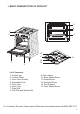
GAS COOKER INSTRUCTION MANUAL Model num ber: RHGC1 Please read these instructions carefully and keep them for future reference For Customer Services, Spare Parts & Warranty Information please call 0845 683 8717 Opening times: Monday - Friday 8am until 8pm Saturday & Sunday 10am until 4pm
Before operating your new appliance please read this instruction manual carefully. It contains important information concerning the safe installation and operation of the appliance. Please keep these operating instructions for future reference. Make sure that the instructions are kept with the appliance if it is sold, given away or moved. Gas cookers must be disconnected and installed by a Gas Safe register engineer. This scheme has replaced the Corgi registration scheme. For details visit www.
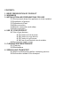
CONTENTS: 1. BRIEF PRESENTATION OF PRODUCT 2. WARNINGS 3. INSTALLATION AND PREPARATIONS FOR USE 3.1 Environment where the appliance is to be installed 3.2 Installation of product 3.3 Adjustment of feet 3.4 Gas connection 3.5 Electric connection and safety 3.6 Gas conversion 4. USE OF YOUR PRODUCT 4.1 Use of gas burners 4.1.1 Control of hob burners 4.1.2 Control of oven burner 4.1.3 Control of grill burner 4.1.4 Use of mechanical minute minder 4.2 Accessories used in oven 5. CLEANING AND MAINTENANCE 5.
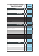
Gas Cooker FREE-STANDING COOKERS SPECIFICATION SHEET RHGC1 Nominal Dimensions Height (Adjustable Feet max. +3.5cm) cm 90 Width cm 50 Depth cm 60 Hob Features Hob Enamel Rapid Gas Burner Ø10cm W 3000 Semi-rapid Gas Burner Ø7.5cm W 1750 Auxiliary Gas Burner Ø5.5cm W 1000 Burner Safety Valves Yes Button Ignition Yes Enamel Pan Supports Standard Gas Conversion Kit Standard Oven Features Oven Type Gas Oven Volume (without fan) Cavity Dimensions (without fan) lt 52.
1.
2. WARNINGS General Safety • These warnings are provided in the interest of your safety. Read this manual carefully before using the appliance. • This appliance has been designed for non-professional, domestic use only.
During Use • When you first run your oven a certain smell will be emanated arising from the insulation materials and the heater elements. For this reason, before using your oven, run it empty at maximum temperature for 45 minutes. At the same time you need to properly ventilate the environment in which the product is installed. • While your appliance operates, its outside surfaces heat up. The interior surfaces of oven and the flue outlet are quite hot.
• Pay attention to the cables of the other electrical devices operating near the appliance, so as not to touch to hot points. • The appliance is not intended to be operated by means of an external timer or separate remote control system. • Do not hang towels, dishcloths or clothes from the appliance or its handles. • Pay attention to the expressions that have figures, while you are reading the operating manual.
3. INSTALLATION AND PREPARATIONS FOR USE ● Before operating your new appliance please read this instruction manual carefully. It contains important information concerning the safe installation and operation of the appliance. ● Please keep these operating instructions for future reference. Make sure that the instructions are kept with the appliance if it is sold, given away or moved. ● Gas cookers must be disconnected and installed by a Gas Safe register engineer.
The appliance can be installed next to furniture units which are no taller than the top of the cooker hob. The wall in direct contact with the back panel of the cooker must be made of non-flammable material. During operation the back panel of the cooker could reach a temperature of 50°C above room temperature. For proper installation of the cooker, the following precautions must be taken: ● The appliance can be placed in a kitchen, dining room or bedsit, but not in a bathroom.
3.3 Adjustment of feet Your product stands on 4 adjustable feet. When the product is placed where it is to be used, check if the product is balanced. If it is not balanced, you can make the adjustment by turning the feet clockwise if required. It is possible to raise the appliance maximum 35mm by the feet. If the feet are adjusted do not move the appliance by dragging, it should be moved by lifting it up. Figure 6 3.
The points that must be checked during fixed gas connection assembly During connections always keep the nut on the gas manifold fixed, while rotating the counter-part. Use spanners of appropriate size for safe connection. For all surfaces between different components, always use the seals provided in the gas conversion kit. The seals used during connection should also be approved to be used in gas connections. Do not use plumbing seals for gas connections.
IMPORTANT: How to wire a 13 amp plug The wires in the mains lead on this appliance are coloured in accordance with the following code: • Green and Yellow – Earth • Blue – Neutral Earth (Green-Yellow) Neutral (Blue) • Fuse (3 Amp) Live (Brown) Brown – Live Cord Clamp Figure 8 As the colours may not correspond with the markings identifying the terminals in your plug proceed as follows.
Spanner Injector Figure 10 Figure 9 Oven/Grill Injectors: The oven and grill injectors are assembled by a single screw that is placed on the tip of the burner. For grill burners, this screw is already visible(Figure 11). Remove the screw, pull the grill burner to yourself and you will see the injector revealed on the rear surface of the oven cavity (Figure 12). For oven burners, open the drawer compartment and you will see the assembly screw below the burner (Figure 13).
To determine the minimum position, ignite the burners and leave them on in minimum position. Remove the with the help of a small screwdriver fasten or loosen the bypass screw around 90 angular degrees. When the flame has a length of at least 4mm, the gas is well distributed. Make sure that the flame does not die out when passing from the maximum position to the minimum position. Create an artificial wind with your hand toward the flame to see if the flames are stable.
4. USE OF YOUR PRODUCT 4.1 Use of gas burners Ignition of the burners To determine which knob controls which burner, check the position symbol above the knob.
Flame safety device: Hob Burners This hob is equipped with flame failure device provide security in case of accidentally extinguished flame. If such a case occurs, the device will block the burners gas lines and will avoid any accumulation of unburned gas. Wait 90 seconds before re-igniting an extinguished gas burner. Oven / Grill Burners Regardless of the model of your appliance, all oven burners are equipped with a gas safety device.
Your hob has burners of different diameters. The most economic way of using gas is to choose the correct size gas burners for your cooking pan size and to bring the flame to minimum position once the boiling point is reached. It is recommended to always cover your cooking pan. In order to obtain maximum performance from the main burners, use pots with the following flat bottom diameters. Using smaller pots than the minimum dimensions stated below will cause energy loss.
please reter to the temperature table below for the temperature references of those numbers. Do not operate the appliance between "Off" position and first temperature marker in the counter-clockwise direction. Always use the oven between maximum and minimum numbers. When turning the oven off, turn the knob in the clockwise direction so that the knob shows "0" position. RHGC1 Preheating POSITION TEMPERATURE 2700C MAX. 2500C • 2400C 5 2200C • 2000C 3 1900C • 1800C 1 1600C MIN.
4.1.3 Control of the grill burner ! CAUTION: Accessible parts may be hot when the grill is in use. Young children should be kept away. Right after you ignite the burner, place the grill heat deflector under the control panel. After that, lift the oven door up slowly until it stops at the semi-open (30 °) position and touches the heat shield. Assembling the heat deflector Hold the heat deflector as the warnings face upwards.
• Never cover the grill pan or grid with foil as this can lead to grill fires. • If your appliance has a grill pan and handle set as an accessory, refer to accessories section for its usage. ! WARNING: Ensure that the grill is turned off before closing the door. 4.1.4. Use of mechanical minute minder 0 Set the desired cooking time by turning timer button clockwise. At the end of this time period, it will make a bell sound, but the oven continues working.
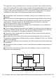
Oven Cavity Rack positions for molded racks 6. Rack 5. Rack 4. Rack 3. Rack 2. Rack 1. Rack Oven Accessories * The accessories of your oven may be different due to the model of your product. Wire grid Wire grid is used to grill or to place different cookwares on it. To locate the wire grid correctly in the cavity, put it to any rack and push it up to the end. Oven Tray Oven tray is used to cook stews, chips, etc. To locate the tray correctly in the cavity, put it to any rack and push it up to the end.
5. CLEANING AND MAINTENANCE 5.1 Cleaning Be sure that all control switches are off, your appliance cooled and the appliance is unplugged before cleaning your oven. Check whether the cleaning materials are appropriate and recommended by the manufacturer before using the cleaning materials on your oven. As they may damage the surfaces, do not use caustic creams, abrasive cleaning powders, thick wire wool or hard tools. In case the liquids that overflow around your oven burn the enameled parts may be damaged.
Cleaning of Gas Cooker - Hob Part • Ensure all switches are off, your appliance cooled and the appliance is unplugged before cleaning. • Lift up the pan supports, caps and crowns of hob burners. • Wipe and clean the back panel with a soapy cloth. • Wash the caps and crowns of hob burners and rinse them. Do not leave them wet, immediately dry them with paper cloth. • After cleaning, make sure that you re-assemble the parts correctly. • Do not clean any part of the hob with metal sponge.
Burner Caps: Periodically, enameled pan support, enameled covers, burner heads must be washed with soapy warm water rinsed and dried. After drying them thoroughly, replace them correctly. Enamelled Parts: In order to keep them as new, it is necessary to clean them frequently with mild warm soapy water and then dry with cloth. Do not wash them while hot and never use abrasive powders or abrasive cleaning materials.
6. SERVICE AND TRANSPORT 6.1 Basic troubleshooting before contacting service If the oven does not operate : • The oven may be unplugged or switched off at the plug. • There has been cut off at power and the fuse box/switch needs to checked. If the oven does not heat : • The heat may be not adjusted with oven's heater control switch. If the interior lighting lamp does not light : • A replacement bulb is needed.
INJECTOR TABLE LPG NG G30 G20 28-30 mbar 20 mbar Gas Category: II2H3+ RAPID BURNER Injector Diameter (%mm) 85 115 Nominal Rating (kW) 3 2.75 Consumption in 1h 218.1 gr/h Consumption in 1h 285.7 lt/h (at 150C and 1013mbar pressure) SEMI-RAPID BURNER Injector Diameter (%mm) 65 97 Nominal Rating (kW) 1.75 1.75 Consumption in 1h 127.2 gr/h Consumption in 1h 166.
For Customer Services, Spare Parts & Warranty Information please call 0845 683 8717 Opening times: Monday - Friday 8am until 8pm Saturday & Sunday 10am until 4pm Customer Service Department Picktree Court Picktree Lane Chester-le-Street Co Durham DH3 3SY Revision 1 This symbol is known as the 'Crossed-out wheelie bin Symbol'. W hen this symbol is marked on a product/batteries, it means that the product/batteries should not be disposed of with your general household waste.