OPERATOR'S MANUAL #4950300 ROUTER MOUNTING KIT (FOR USE WITH THE BT3000 TABLE SAW) CONGRATULATIONS AND THANK YOU FOR BUYING THIS RYOBI ROUTER MOUNTING KIT. Your new #4950300 Router Mounting Kit has been designed for use with the RYOBI BT3000 Table Saw. It has been engineered and manufactured to Ryobi’s high standards for dependability, ease of operation, and operator safety. This kit gives you the capability of mounting a router on the accessory table of your BT3000.
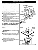
RULES FOR SAFE OPERATION ■ READ THESE INSTRUCTIONS THOROUGHLY before assembling or using this router mounting kit. ■ READ THE INSTRUCTIONS AND RULES OF SAFE OPERATION FOR THE BT3000 TABLE SAW before operating your saw with this kit. ■ KEEP ASSEMBLY AREA AND WORK AREA CLEAN. Cluttered areas and benches invite accidents. ■ ALWAYS WEAR SAFETY GLASSES. Everyday eyeglasses have only impact-resistant lenses; they are NOT safety glasses. ■ DO NOT USE THIS PRODUCT WITH OTHER EQUIPMENT OR FOR OTHER PURPOSES.
UNPACKING WARNING: WARNING: Attempting to assemble the Router Mounting kit or to use in any way without obtaining any missing parts and installing them correctly, could result in an accident resulting in possible serious injury. Do not attempt to operate this tool until you have read thoroughly and understand completely all instructions, safety rules, etc. contained in this manual. Failure to comply can result in accidents involving fire, electric shock, or serious personal injury.
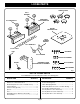
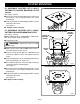
LOOSE PARTS THROAT PLATES 5/16 in. WASHERS GUIDE FENCE WITH GUIDE BLOCK 1/2 in. KNOB BOLTS ROUTER MOUNTING PLATE TABLE CLAMPING BRACKET 3/4 in. KNOB BOLT 5/16 in. T-NUTS POST M8 SCREWS 5/16 in. WASHER #10-32 SCREWS SPACER GUARD/DUST COVER WITH PIVOT ASSEMBLY #5/16-18 SCREWS #1/4-20 SCREWS Fig. 1 LIST OF LOOSE PARTS Your #4950300 Router Mounting Kit includes the following parts: DESCRIPTION DESCRIPTION QUANTITY Guide Fence with Guide Block ................................
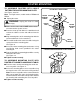
ASSEMBLY Read these instructions completely before beginning assembly of this kit. ROUTER MOUNTING T-NUT SHOWN BETWEEN ADJUSTMENT SCREWS WARNING: The saw's motor cord must be disconnected from the receptacle on the saw when using this kit. The power cord of the router must be plugged into the receptacle on the saw. The saw's master switch must be used to turn the router ON and OFF. Failure to do so could result in serious injury.
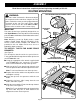
ROUTER MOUNTING TO INSTALL GUIDE FENCE BRACKETS: GUARD/DUST COVER WITH PIVOT ASSEMBLY CARRIAGE BOLT (NOT SHOWN) KNOB NUT ■ To install the guide fence brackets, align each bracket with two of the T-nuts on top of the rip fence. See Figure 4. Note: Use the front two T-nuts and the back two Tnuts leaving the one in the middle empty. ■ Secure the guide fence brackets to the rip fence with 5/16 in. washers and the 5/16 in. x 1/2 in. knob bolts.
ROUTER MOUNTING TO ASSEMBLE ROUTERS WITH 2-HOLE PATTERN TO ROUTER MOUNTING PLATE (cont'd): 2–HOLE ROUTER WITH MOUNTING PLATE ATTACHED See Figures 5 and 6. ■ Secure the router mounting plate to the router using two 5/16-18 x 3/4 in. bolts provided in the router mounting kit. ■ Properly installed, the mounting plate will be securely attached to the router. See Figure 6. ■ Tighten screws securely. Fig. 6 TO ASSEMBLE ROUTERS WITH 3-HOLE PATTERN TO ROUTER MOUNTING PLATE: See Figures 7 and 8.
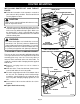
ROUTER MOUNTING TO ASSEMBLE ROUTERS WITH 4-HOLE PATTERN TO ROUTER MOUNTING PLATE: See Figures 9 and 10. Note: For Ryobi routers, model numbers RE600 and RE601. ■ Unplug the router. WARNING: ROUTER WITH 4–HOLE PATTERN ROUTER MOUNTING SCREWS Unplug the router to avoid ROUTER BASE possible injury. ■ Make sure the router switch is OFF and the router is not connected to a power source.
ROUTER MOUNTING INSTALLING ROUTER BIT AND THROAT PLATE: THROAT PLATE #1/4-20 SCREWS (PROVIDED) ■ Follow the instructions in the operator's manual of your router for this procedure. Install router bit and securely tighten in collet. ACCESSORY TABLE CAUTION: Make sure the router bit will not strike the accessory table or any metal surface. ■ Select the correct size throat plate for the size of the router bit. Align the tab on the throat plate with the slot in the accessory table and snap in place.
ROUTER MOUNTING FINAL ASSEMBLY: After the router mounting parts have been assembled, your setup should be similar to Figure 13. DIRECTION OF FEED IS FROM RIGHT TO LEFT AGAINST SHARP EDGES OF ROTATING BIT ■ Compare your setup and make any necessary adjustments. ■ Recheck all knob bolts, attachments, etc., and securely tighten if necessary. FINAL PREPARATION FOR OPERATION See Figure 13. ■ Adjust dust cover so that it will not come in contact with workpiece during a cutting operation.
NOTES Page 11
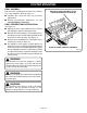
#4950300 ROUTER MOUNTING KIT 5 3 4 6 5 8 7 10 9 3 4 11 2 1 3 12 13 21 15 20 4 14 24 22 19 23 16 17 18 Page 14
REPLACEMENT PARTS Now that you have purchased your Router Mounting Kit, should a need ever exist for repair parts or service, simply contact your nearest Ryobi Authorized Service Center. Be sure to provide all pertinent facts when you call or visit.
OPERATOR'S MANUAL #4950300 ROUTER MOUNTING KIT (FOR USE WITH THE BT3000 TABLE SAW) RYOBI TECHNOLOGIES INC. 1428 Pearman Dairy Road Anderson SC 29625 Post Office Box 1207 Anderson SC 29622-1207 Phone 1-800-525-2579 www.ryobitools.