
Owner manual


Page 5
Read these instructions completely before beginning assembly of this kit.
WARNING:
The saw's motor cord must be disconnected from
the receptacle on the saw when using this kit. The
power cord of the router must be plugged into the
receptacle on the saw. The saw's master switch
must be used to turn the router ON and OFF.
Failure to do so could result in serious injury.
IMPORTANT
This router kit has been specifically designed for use
with Ryobi Routers. The hole pattern on the mounting
plate has not been drilled to accommodate other routers
on the market.
Note: Mounting screws for Ryobi routers, model
numbers R160, R165, RE170, RE170VS, R175,
RE175, R180, RE185, RE600, and RE601 are
provided in this kit. Model R175 must also use
#4830175 depth control kit.
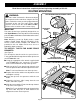
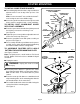
TO INSTALL T-NUTS FOR GUIDE FENCE
BRACKETS:
See Figure 2.
This kit requires that five of the six special 5/16 in.
T-nuts provided fit in the top channel of the rip fence on
your BT3000 table saw.
■ Using the appropriate allen wrench supplied with
your BT3000 table saw, remove the rear adjust-
ment screw and washer on top of the rip fence.
■ Slide one of the T-nuts into the top channel of rip
fence and place between the two adjustment screws.
Note: T-nuts install from the rear of the rip fence.
■ Replace the washer and the rear adjustment screw
and tighten securely.
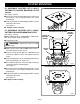
■ Check the rip fence for squareness with the saw
blade.
■ Unlock the rip fence, slide it away from the saw
blade, and lock it in place.
■ Slide the four remaining T-nuts into the top channel
of rip fence.
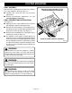
See Figure 3.
Note: Five T-nuts should be in the top channel of the
rip fence with only one of them between the
adjustment screws on the rip fence.
Fig. 2
Fig. 3
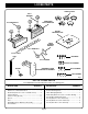
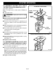
ROUTER MOUNTING
T-NUT SHOWN BETWEEN ADJUSTMENT SCREWS
ADJUSTMENT
SCREW
T-NUT
WASHER
RIP FENCE SHOWN
LOCKED AGAINST SAW BLADE
INSTALL T-NUTS FROM REAR OF RIP FENCE
T-NUT
ASSEMBLY