
Owner manual


Page 7
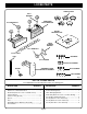
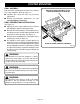
Fig. 6
Fig. 7
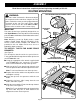
Fig. 8
ROUTER MOUNTING
TO ASSEMBLE ROUTERS WITH 2-HOLE
PATTERN TO ROUTER MOUNTING PLATE
(cont'd):
See Figures 5 and 6.
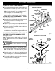
■ Secure the router mounting plate to the router using
two 5/16-18 x 3/4 in. bolts provided in the router
mounting kit.
■ Properly installed, the mounting plate will be securely
attached to the router.
See Figure 6
.
■ Tighten screws securely.
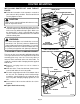
TO ASSEMBLE ROUTERS WITH 3-HOLE
PATTERN TO ROUTER MOUNTING PLATE:
See Figures 7 and 8.
Note: For Ryobi routers, model numbers R160, R165,
RE170, RE170VS, R180, and RE185.
■ Unplug the router.
WARNING: Unplug the router to avoid
possible injury.
■ Make sure the router switch is OFF and the router is
not connected to a power source.
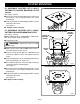
■ Place the router upside down on a workbench and
remove the subbase screws and subbase from the
router.
■ Align mounting holes of the mounting plate with the
three threaded holes in router base.
■ The switch handle of the router should be facing the
squared end of the mounting plate.
See Figure 7.
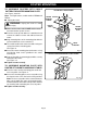
■ Secure the router mounting plate to the router using
three 5/16-18 x 3/4 in. bolts provided in the router
mounting kit.
■ Properly installed, the mounting plate will be securely
attached to the router.
See Figure 8.
■ Tighten screws securely.
ROUTER
MOUNTING
SCREWS
FRONT
OF ROUTER
ROUTER
MOUNTING
PLATE
ROUTER WITH 3–HOLE PATTERN
3–HOLE ROUTER WITH MOUNTING PLATE ATTACHED
2–HOLE ROUTER WITH MOUNTING PLATE ATTACHED
ROUTER
BASE