(Revision: May 2010)
ACKNOWLEDGEMENTS This manual was prepared by the members of the 2008 Safety Committee: Dave Young, Randy Pensabene, Roger Tripp, Irv Turnbull, Ted Girvan Additional contributors to this manual include: Ray Hohenberger, Jerry Sivin, Bill Hartmann, Dick Gelbaugh, Larry Mart, David Freiborg, Bill Neal, Don Webster REVISIONS All suggested changes, edits and/or additions to this document should be submitted in writing by one of the following methods: a.
REVISION September 2009 May 2010 COMMENT • Section 3.3 Woodshop Materials & Processes: Added forbidden materials – painted wood & sealers • Section 6 Planer: Updated for KUFO CC-824B • Section 5 Jointer: Updated for new cutter head, 1/16th inch max. depth adjustment & safety issues • Changed email address to send suggested changes, edits and/or additions to this document • Section 2.1.
Table of Contents 1. INTRODUCTION ............................................................................................................................................. 1 1.1. 1.2. 1.3. 1.4. 2. SAFETY – GENERAL ........................................................................................................................................ 2 2.1. 2.2. 3. PURPOSE OF WOODWORKERS CLUB .............................................................................................................
7.2. AVOIDING KICKBACK! – TABLE SAW (READ THIS SECTION!) ................................................................................26 7.2.1. Table Saw Guard ...............................................................................................................................26 7.2.2. Don’t Be Afraid to Ask .......................................................................................................................26 7.2.3. Kickback when RIPPING or CROSSCUTTING ......................
11.2. SETUP & USE – SCROLL SAW.............................................................................................................................55 11.2.1. Patterns & Photocopies .....................................................................................................................55 11.2.2. Installing a Blade ...............................................................................................................................55 11.2.3. Helpful Hints on Blade Tension .......
16.5.1. Tailstock Movement ..........................................................................................................................79 16.5.2. On/Off Switch ....................................................................................................................................79 16.5.3. Spur Center ........................................................................................................................................79 16.5.4. Face Plate .........................
19.2.8. 19.2.9. 19.2.10. 19.2.11. 19.2.12. 19.2.13. Installing & Removing the Bit ............................................................................................................98 Adjusting Plunge Base .......................................................................................................................98 Starting & Stopping the Motor ........................................................................................................100 Using the Router ...................
27.2. SETUP & USE – WIDE DRUM SANDER...............................................................................................................114 27.2.1. Turn-On Procedure ..........................................................................................................................114 27.2.2. Turn-Off Procedure ..........................................................................................................................114 28. 28.1. 28.2. 29. SANDER, DRUM (RYOBI WDS1600) ......
1. INTRODUCTION 1.1. Purpose of Woodworkers Club The purpose of the Woodworkers Club, a Chartered Club of Sun City Texas, is to encourage and support the craft of woodworking among its members by sponsoring programs, exchange of information about woodworking and other relevant activities. It is also our responsibility to fund and manage safe operations of the Woodshop for use by its members in Sun City Texas. The Club bylaws can be found at: http://www.sctxwoodshop.com/bylaws.htm . 1.2.
2. SAFETY – GENERAL The WOODSHOP SAFETY POLICY is to keep all the blade guards in place – for the table saws, for the band saws, for the jointer. If an operation requires the removal (or disabling) of a guard, they must be replaced (or restored) immediately after the operation is complete. 2.1. Woodshop Rules on Attire & Recommended Safety Gear When in the Woodshop, it is important that the woodworker be dressed appropriately.
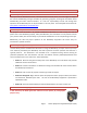
Recommended Gear: The following are not required by the Woodshop, but are recommended: • Safety Glasses: First and foremost, when working with any woodworking tools, we recommend the wearing of safety glasses. For many operations small pieces of stock can be propelled in nearly any direction. Even worse, if a blade breaks, the possibility exists that a piece could come loose. Your eyesight is too valuable to take chances to be woodworking without protective eye wear.
finish the cut or turn off the equipment before diverting your attention. Too often, injuries occur because the operator was distracted, even for only a moment. DON’T FLICK WOOD PIECES with your Finger: When using a saw, there will often be very small pieces of stock that are cut off during the cutting process. Do not attempt to flick these away from the blade with your fingers. Use another piece of stock or a push stick, preferably with the blade stopped.
3. TRAINING & WOODSHOP USAGE 3.1. Additional Training & Information If you are not thoroughly familiar with the operations of a particular machine or tool, obtain advice from a shop Monitor or seasoned woodworker.
• Patterns for many projects • Specifics about wood tools and power equipment • Jigs • Wood carving • Finishing While not every issue of each periodical is available, many are.
• About.com: http://woodworking.about.com/od/safetyfirst/Using_your_Woodworking_Tools_Safely.htm • American Woodworker Magazine: http://www.americanwoodworker.com • Newwoodworker.com Tips & Tricks: http://www.newwoodworker.com/tipstrksdir.html • Popular Woodworking Magazine: http://popularwoodworking.com • Woodsmith, ShopNote & Workbench Magazines Woodworker’s Forum: http://www.woodnet.net/forums/ • WOOD: http://www.woodmagazine.com/ • Woodcraft Magazine: http://woodcraft.
3.3. Woodshop Materials & Processes See the Club’s GENERAL SAFETY PROCEDURES AND RULES on our web site (http://www.sctxwoodshop.com) for additional and more current details of what is and is not allowed. 3.3.1. Forbidden Materials ONLY NEW/UNUSED WOOD is allowed to be machined in the Woodshop. Therefore, the following is a comprehensive list of materials that are NOT allowed to be machined in the Woodshop: • Used wood NOTE: Lumber with unfound nails, stones, bards, screws, etc.
Further, if you are leaving wood for any reason, you must stow your materials out of the way, and you must leave the following information on a piece of paper taped on the wood (especially important if you leave the shop while your glue is setting up) – information that includes: 1) Your name 2) Your phone number 3) If clamped, an indication as to when the clamps can be taken off (no longer than 4 hours after clamping) 4) An indication as to when you left the shop and when you plan to return 3.3.4.
4. How to Prepare a Board 4.1. Reading Grain Orientation Improper feed direction can ruin the work piece and can represent a danger to the woodworker! The grain must slope away from the cutters edge. Be sure you know which way the cutter is turning! If wood is machined in the wrong direction: • The edges of grain lines can lift or separate, requiring additional sanding to achieve a smooth surface. • A cutter can catch the edge of a grain line and may contribute to kickback.
• In the rare instances when feed direction shows no difference, watch the results produced in successive passes as grain orientation usually changes as wood is removed. The time and effort spent in reading grain orientation in a piece of wood is more than offset by eliminating unnecessary steps in surface preparation and by reducing the potential of a kickback or board fracture.
• For bad edges, use a long straight edge or snap a chalk line to mark the edge just inside the defect. Most often this cut line is positioned to minimize the amount of wood to be removed, but it can be also angled slightly so the finished edge is more closely aligned with the grain of the wood. After marking, use a bandsaw, circular saw or jigsaw to remove and straiten the defective edge. Then take the new edge to the jointer to perfect the edge with considerably less effort and loss of wood.
The next two steps can be performed in either order, just make sure to put the flat face down if you haven’t planed the 2nd face of the board! 5) Fifth, get the second edge parallel to the first edge: Once the board has three good sides (two faces and one edge), make a rip cut on the fourth side (remaining uneven edge) using the table saw by having the “flattened/squared” edge against the table saw fence. (See Section 7. Table Saw for details of how to use this piece of equipment.
5. JOINTER, SURFACE (12” General International 80-300M2) A jointer can machine one face and one edge of a board perfectly flat and straight and square to each other. It cannot make surfaces parallel to each other. That is the job of the thickness planer for surfaces and the job of the table saw for edges. 5.1. Safety Precautions a. DO NOT perform face jointing operations on stock smaller than 12” long by 3/4” wide, or joint any edges less than 12” long by 1/4" thick. b.
l. AVOID AWKWARD OPERATIONS AND HAND POSITIONS. A sudden slip could cause a hand to move into the cutterhead. m. NEVER PERFORM LAYOUT, ASSEMBLY, OR SET-UP WORK on the table/work area when the machine is running. A sudden slip could cause a hand to move into the cutterhead. Severe injury can result. 5.2.
The jointer setup involves four components as follows: 1) In order to use the jointer, the outfeed or rear table must be perfectly aligned with the knives in the cutterhead. • This is performed by an experienced member of the maintenance team ONLY and the left wheel which controls this setup CANNOT BE ADJUSTED by the general user. 2) Be sure to check how deep the cut will be: • The vertical distance between the infeed and outfeed table determines how much you will cut (or joint) off your wood.
direct contact with the flat side of the stock as it is passed through the unit. It is WRONG for operators to use the pusher block on the back of the stock with their right hand while pushing down on the front portion of the stock with their left hand. It cannot be stressed enough that operators must use one of the yellow hold down blocks in the FRONT with the left hand AND a pusher block in the BACK of the stock.
should be concentrated over the outfeed table. That way the knives can extend that machined-flat portion and minimize the amount of wood that is removed during however many cuts needed to eliminate the rest of the defect. o • Another technique that can help true a slightly distorted board is swapping ends between the first few cuts.
6. PLANER, SURFACE/THICKNESS (24” KUFO Seco SK-824WP-VS, 16” LaGuna Platinum Series 16”) AFTER one face of a board has been flattened using the jointer, a planer is used to get the two faces of the board parallel to each other. Then, if needed, use the planer to reduce the thickness of that board. 6.1. Safety Precautions a. NEVER ALLOW ANY PART OF YOUR BODY TO PASS BEYOND THE FRONT EDGE OF THE TABLE BED WHEN THE MACHINE IS IN OPERATION.
6.2. Setup & Use – 24” KUFO Seco Planer Surface plane the workpiece on a jointer until it is flat on one side. This will ensure that it sits flat on the planer table during operation. To obtain even, uniform thickness across the length of a board, the stock being planed must have one face that has already been machined perfectly flat on the jointer and the stock must be fed with this flat face against the table. 6.2.1. Adjusting the Depth of Cut a. Cut capacity: – WORKPIECE MUST BE 12” or longer – Max.
NOTE: Anytime you switch directions with the handwheel, there will be a small amount of backlash. Always approach the final setting from the same (clockwise) direction for best accuracy. g. To get an accurate cut on a wide board, do a test cut and measure the four corners of the board. If there is a significant variation, maintenance should be done on the machine to level the feed tables with the cutterhead. 6.2.2. Operating the Planer a. Start the planer by pushing the START button. b.
6.3. Setup & Use – 16” LaGuna Planer Surface plane the workpiece on a jointer until it is flat on one side. This will ensure that it sits flat on the planer table during operation. To obtain even, uniform thickness across the length of a board, the stock being planed must have one face that has already been machined perfectly flat on the jointer and the stock must be fed with this flat face against the table. 6.3.1. Adjusting the Depth of Cut a. Cut capacity: – WORKPIECE MUST BE 12” or longer – Max.
• Place the push/pull Geerbox knob/handle to NEUTRAL (Middle) position. CAUTION: Geerbox must be in NEUTRAL prior to engaging power. • Open the RED RESET/STOP button by slightly twisting to right. • Depress the GREEN START button to engage power • Place the push/pull Geerbox knob/handle IN or OUT to engage the in-feed and out-feed power o IN for 16 FPM (Hardwood) o OUT for 20 FPM (Softwood). b. Place the flat side of the board down on the table and feed the workpiece through the planer.
7. SAW, TABLE (10” Powermatic 66-TA, Delta 36-L53L, Delta 34-806) (NOTE: Portions of the information presented in this section were taken from the Powermatic & Delta Operating Manuals.) The Table Saw is the most versatile machine in the Woodshop and is used to rip, square, miter and groove wood pieces. Before making any cut, stop and think the task through. The versatility of the table saw usually provides alternative ways of performing nearly any cut.
• For some tasks the guard may require removal. If removed, you must replace the guard before leaving the saw. d. WITH POWER OFF, check the blade for sharpness and secure fastening to the arbor before machine is turned on. Blade should be free of rust and pitch. e. ADJUST BLADE to be no more than 1/8” above the surface of the wood being cut. f. MAKE SURE that fence or slide will not pass through the saw blade. g. DO NOT CUT badly warped material. h. KEEP HANDS OUT of the path of saw blade. i.
• Cutting across the grain is crosscutting. Never use a fence or fence system for cross-cutting. Instead, use a miter gauge. u. BEFORE YOU LEAVE: 7.2. • Shut off power, lower blade below table, and clean the saw before you leave it. • Verify all guards are in place, or reinstall guards. Avoiding Kickback! – Table Saw (READ THIS SECTION!) Kickbacks happen when the saw blade catches the workpiece and violently throws it back toward the operator causing serious injury to the operator or someone nearby.
c) Kickback can occur when the board is pinched between the rear of the blade and the rip fence. The fence should be parallel with the blade. Never allow the fence to be closer to the rear of the blade than the front. d) Cutting a warped or twisted board along the rip fence is dangerous because it can get pinched between the fence and blade. Prepare your board using the Jointer so you have a stable flat surface and one square edge before going to the Table Saw.
RIP CUT: If you allow the stock to twist or skew, as soon as it reaches the back edge of the blade, the up-running teeth will launch it at you, in the direction of the blade rotation (red arrow). (Kickback diagrams courtesy of: http://www.raygirling.com/kickback.htm) 7.3. Setup – Table Saw The setup and operation for all three table saws are essentially the same. 7.3.1. Changing the Blade • Disconnect machine from power source.
the LEFT for the Powermatic and 45° to the RIGHT for the Delta. • The lock knobs (D) are used to lock the setting of the handwheels. (NOTE: Only a small amount of force is required to lock the mechanism securely. Any added force merely puts unnecessary strain on the locking device.) 7.3.3. Installing Splitter Guard Assembly • Place the two flanges of the splitter assembly onto the screws as shown. • Front Shield Snug the screws. NOTE: Make sure the front shield faces in toward the blade.
7.4. • Not using the splitter when ripping or not maintaining alignment of the splitter with the saw blade. (WARNING: The splitter is removed when you remove the blade guard!) • Using a dull saw blade. • Not maintaining alignment of the rip fence so that it tends to angle toward instead of away from the saw blade front to back. • Applying feed force when ripping to the cutoff (free) section of the work piece instead of the section between the saw blade and fence.
against the fence throughout the cut. That is safer and produces a much smoother, more accurate, cut edge at the same time. • Push stick. The Woodshop has three types of additional pushers in the shop, as pictured below. You hook the notch over the wood and push it through, hoping it doesn’t turn into the blade before enough of it reaches the splitter. The problem with the design of this type of pusher is that it affords virtually no directional control over the wood.
7.6. Rip Cuts Ripping is where the workpiece is fed with the grain into the saw blade using the fence as a guide and a positioning device to ensure the desired width of cut. While all table saws are capable of rip cuts, our preference is that the Delta saws be the primary ones used for rip cuts. Keys to safe, accurate rip cuts include: 1) Have a sufficiently long straight edge against the fence.
c) Before starting the cut, raise the blade so that it is about 1/8” higher than the top of the workpiece. d) When ripping, feed force should always be applied between the saw blade and the fence. • In ripping, use LEFT hand to hold the board down against the fence or fixture, and the RIGHT to push it into the blade between the blade and the fence. Never push in a location such that the RIGHT/pushing hand is in line with the blade.
o • NEVER lift your hand up during a cut! Another tip for making accurate miter cuts, particularly steep ones, is to make an initial cut about 1/16” over the length needed. Then carefully make a final cut on the layout line. The initial cut removes most of the waste, leaving less than the blade’s width to trim away. This greatly reduces the force of the blade on the wood and makes holding the wood absolutely still during the cut easier.
7.7.2. Making a Crosscut or Miter Cut Mitering is the same as crosscutting except that the miter gauge is locked at an angle other than 0°. Follow the procedure below for either type of cut. CAUTION: Miter angles greater than 45° may force the guard into the saw blade and damage the guard. Before starting the motor, test the operation by feeding the workpiece into the guard. If the guard contacts the blade, place the work piece under the guard, NOT TOUCHING THE BLADE, before starting the motor.
7.8.1. Bevel crosscutting Bevel crosscutting is the same as crosscutting except the bevel angle is set to an angle other than 0°. Always use the miter slot which allows the blade to tilt away from the miter gauge and your hands to avoid a binding action between the saw blade and the table top. When beveling with the miter gauge, the workpiece must be held firmly to prevent creeping. 7.8.2.
Another benefit of the sacrificial fence is that if made tall enough, a feather board can be clamped to it to help keep the wood being cut flat on the table to ensure a consistent depth dado. We do not currently have one in our Woodshop, but one can be made. To make a dado or rabbet cut: a) Remove blade guard and splitter assembly. b) Stack the saws and cutters and install: • The cutters are heavily swaged and must be arranged so that the teeth do not hit each other during rotation.
8. SAW, BAND (15” General International 490, 14” LaGuna LT14-3000 Series, 20” Delta 28640/641) Band saws are capable of performing a wide range of cuts such as ripping, cross cutting, beveled cuts, curves and re-sawing (slicing thick boards into several thinner boards). The Woodshop has the following bandsaws: • One 15” General International 490 is setup with a 1/4" blade for fine turns and has a fence system. • One 15” General International 490 is setup with a 3/8” blade and a fence system.
b. ADJUST UPPER BLADE GUIDE to about 1/8” to 1/2" above the material being cut. This gives you a better cut and puts less stress on the blade. c. HOLD WORKPIECE firmly against table and feed into blade at a moderate speed. d. DO NOT attempt to saw wood that does not have a flat surface unless a suitable support is used. e. USE A SUITABLE SUPPORT fixture for large material. f. TURN OFF SAW if wood needs backing out of an incomplete or jammed cut. g.
• Start up the band saw and wait until the motor is at full speed before beginning any cut. • Place one hand should be on each side of the stock to guide it through the blade. Never place your hand directly in the cut line, even if it is more than 3” away. Use a push stick if you must hold the stock closer than 3”. Also, never reach across the band saw. • Do not attempt to "free-hand" the stock in mid-air. The stock must remain flat on the surface of the table at all times during the cut.
• 8.3. Do not attempt to flick these away from the blade with your fingers! Use another piece of stock or a push stick. Often this is not necessary, as the next cut will push the piece safely away from the blade. Once the cut off piece is safely away from the blade, push it off of the table. Never leave loose pieces on your table that could impede your cut. Setup & Use – 14” LaGuna Band Saw with Drift Master Fence CAUTION: Clamp Locking Screws on this unit MUST NOT be over-tightened. a.
• o Slide the fence and scrap stock forward and secure the single Fence Clamp Locking Screw. o Turn band saw ON and make a 1 inch test cut in scrap stock. Do not remove stock. o Depress Brake Pedal to turn power OFF and stop blade motion. o Check variance of space on either side of back of blade. Alignment is complete when back of blade is centered in test cut. Re-align as necessary: o Loosen the two Clamp Screws located on the top of the Fence Mounting Bracket.
o As with any re-saw blade, the surface finish of the cut will not be completely smooth. (NOTE: Adjust thickness to allow for finish sanding to final desired thickness) o The small Hand Wheel attached to and located at the back of the Screw Drive Assembly will provide the proper adjustment for thickness of cut. 8.4. The single Clamp Fence Locking Screw must be: • Loosened prior to making any adjustment to the fence. • Tightened when the adjustment has been completed.
CAUTION: When cross-cutting logs, be sure that you DO NOT use the fence (just as when cross-cutting with the table saws), you can bind and break the blade! c. Re-sawing Boards: Set the fence to the required thickness and use a push block. d. Sawing Logs: • Ideally, you’ll have a sled to hold onto the log and prevent it from rolling while you cut and providing stability for these difficult cuts. • As of the writing of this manual, the Woodshop does not have such a sled, but one can be made.
9. SAW, MITER – DUAL BEVEL COMPOUND (12” DeWALT DW716) & DUAL BEVEL COMPOUND SLIDING (12” DeWALT DW718) The ability to precisely angle and bevel the saw before cutting into the wood gives the compound miter saw its versatility. When you need to make a precise, compound angle cut on the end of a piece of stock, few tools are as easy to use. 9.1. Safety Precautions a. DO NOT perform any operation freehand. b. KEEP GUARD IN PLACE at all times. c. AVOID CUTTING badly warped material. d.
b) Set the saw’s miter and bevel angles c) Secure the stock firmly against the fence d) Line up the mark with the laser line and the saw blade will cut to the right of the laser line 9.3. Setup & Use – Sliding Compound Miter Saw 10.2.1. Capacity & Angles The sliding compound miter saw is operated the same as the compound miter saw, but has the ability to accommodate larger boards: a. Bevels 0° - 48° with positive stops at 0°, 22.5°, 33.9° and 45° in both directions. b.
c. • Loosen Bevel Latch Lock Handle. • Unlock a Bevel Latch Lever (one on each side). • Move saw left or right to desired angle of cut. • Lock Bevel Latch Lever. Basics of making a cut: • Line up the cut mark with the blade. • Depress trigger switch to turn ON: • o Allow blade to reach full RPM before making cut. o Hold stock firmly against table and fence. o Do not force blade down – Lower saw head smoothly and slowly. Release the trigger switch to turn OFF. o d.
10. SAW, PANEL (64” Safety Speed Cut 6400) (NOTE: Portions of the information presented in this section were taken from the Safety Speed Cut Operating Manual.) 10.1. Safety Precautions a. NEVER leave the saw running unattended. b. DO NOT overreach. Maintain control. c. DO NOT force the tool into workpiece. d. AVOID kickback by keeping blade from binding. e. IF the saw is stopped in mid-cut, allow the blade to stop completely. Then back up the saw before restarting. f.
10.2.1. General Operating Tips When you feed the material through the tool horizontally, or move the carriage over the material vertically, do it slowly, smoothly, and (whenever possible) without stopping. Overfeeding results in poor-quality cuts, shortened blade life, and motor overloading. Be careful when setting material onto the rollers. Do not drop heavy material onto the rollers or damage to the rollers may result.
e. Make certain that the workpiece is adequately supported and stable in the machine. The workpiece can be held with one hand; do not hold the workpiece so that your hand is anywhere behind the carriage or guides or in the path of the saw blade. f. Start the motor (by pulling the outrigger and locking it in the on position) and allow it to reach full speed before beginning the cut. (Stop the motor by pressing the same switch in.) g.
until they snap into the appropriate holes. The rip measurement is set at the factory for cutting right to left. b. Adjust the position of the spring-loaded saw foot to the thickness of the material so that it gently presses on the face. Use the two adjusting knobs located above and below the saw motor. c. Select the height of the saw blade above the rollers. Raise or lower the carriage until the height index tab is aligned with the corresponding dimension on the vertically mounted ruler.
h. As the workpiece passes across the machine, move to the other side and complete the cut by pulling the workpiece past the saw blade. Support the upper piece to keep it from pinching the blade or the kerf protector, or falling away from the machine. NOTE: When doing rip cuts, one gets the most accurate cut if 1/8” shims are inserted along the way – to keep the top part of the wood from binding the blade. i. Once the cut is complete, turn off the motor and wait for the blade to come to a full stop.
11. SAW, SCROLL (30” General International Excalibur EX30) (NOTE: Portions of the information presented in this section were taken from the General International Excalibur Operating Manual.) A scroll saw is a small electric or pedal operated saw useful for cutting intricate curves; it is capable of creating curves with edges.. 11.1. Safety Precautions a. CLEAR TABLE before turning saw “on”. DO NOT cut material too small to be safely supported or handled.
m. NEVER BACK A BOUND BLADE OUT OF A KERF with the saw running. Turn the saw "OFF", disconnect the saw from the power source, wedge the kerf and remove the blade. Breaking blades can cause injury. Page 54 Power Equipment Usage Manual (Rev.
11.2. Setup & Use – Scroll Saw The scroll saw uses two parallel link arms, one above and one below the table, to drive the blade – since both arms drive the blade with equal force, minimal blade deflection makes cuts more precise. • ON/OFF foot switch controls the variable speed, constant torque motor. • Cuts to center of 5' long workpieces with 30" throat; material up to 2" thick.
11.2.3. Helpful Hints on Blade Tension Determining correct blade tension is somewhat subjective. It is learned through experience and is somewhat dependant on personal preference. A properly tensioned blade will last longer and be much less likely to break prematurely. If the blade tension is too loose, you will notice that the blade will have a tendency to drift a lot or slip off-line when cutting and you may also experience excessive vibration or unusual noise.
• Slower speeds also work better with very thin blades, or when cutting most metals as well as for brittle or delicate material such as fine veneers. • Some wood species will have a tendency to burn quicker at higher blade speeds. To avoid additional sanding later, reduce blade speed and feed speed at the first signs of burn marks on the workpiece. 11.2.5. Making the Cuts a. Turn on the saw and set the speed controller to the desired blade speed. b.
12. SAW, TABLE – (3 ¼” Microlux 80463) Even though this is smaller than the machines on the general shop floor, all the same precautions apply. This machine can cut you and give you kickbacks just as much as the saws on the floor. 12.1. Safety Precautions a. CHECK the BLADE for sharpness and secure fastening to the arbor before machine is turned on. b. ADJUST BLADE height so it is approximately 1/8” above the surface of the wood being cut. c. KEEP HANDS out of the path of saw blade. d.
12.2. Setup & Use – 3 ¼” Table Saw This saw can be used for either CROSSCUTS or RIPCUTS.
13. BISCUIT CUTTER/ PLATE JOINER (Porter-Cable 557, Ryobi JM81, Ryobi DBJ50) (NOTE: Portions of the information presented in this section were taken from the Porter-Cable Operating Manual.) This specialized mini-saw cuts thin slots in the edges of wood to hold a biscuit, which is used to hold two pieces of wood together. You can use biscuit joinery for a number of different types of joints. Smaller biscuits work well for strengthening miter joints and corner joints.
Use the largest size biscuit when working with large projects, as this will provide the greatest amount of strength to the joint. In most cases, use #20 biscuits, but when working on narrower material, switch to smaller biscuits where appropriate. 13.3. Setup & Use – Biscuit Cutter Practice Cuts Highly Recommended! After each set-up or adjustment to the tool, make several practice cuts in scrap material to verify desired operation. 13.3.1. To Start & Stop Tool a. Connect tool to power circuit. b.
b. The depth scale (C) indicates the distance from the top edge of the workpiece to the blade: NOTE: The bottom line on scale (C) begins at 1/4" and all lines are in 1/16" increments. • The line across the center of the index block (D) indicates the distance to the center of the blade. • The top edge of the index block (D) indicates the distance to the bottom of the blade. • The bottom edge of the index block (D) indicates the distance to the top of the blade.
Fig. 5 Fig. 6 Fig. 7 Fig. 8 13.3.5. Positioning Grooves for Biscuits The number of grooves (biscuits) used in a joint may be varied to provide the strength required for the particular application. Typically, the center of the first groove is positioned approximately 2” from the edge of the work with additional grooves spaced at 3” to 6” on centers, or for longer boards every 12” to 18“. In most cases, one line of grooves (biscuits) positioned approximately along the centerline of the material is used.
Fig. 9. 13.3.6. Butt Joint – Connecting the Edges of Two Boards Begin by checking the boards to make sure that they will line up properly. a. The two pieces of stock should be of the same thickness and should make consistent contact across the entire length of the joint. Whenever possible, complete a pass through a jointer to machine-plane the two pieces of stock to ensure that you have two straight edges.
b. Next, choose your biscuit size, #20 is the larger biscuit and is normally used for boards that are about 3/4" thick. c. With a pencil, make a few small, evenly-spaced marks across the joint to denote the location of each biscuit on each board. Now, set one board to the side. d. Using the biscuit joiner, place the guide fence flat on the top of the stock and line the cutting guide with one pencil mark.
easiest way is to squirt some glue into the slot and then run a glue brush through the slot until the glue is evenly coated on all surfaces. j. Use clamps to hold the joint while the glue dries, but take care that you don't tighten the clamps so much that you squeeze all of the glue out of the joint. k. Remove dust from the dust bag. 13.3.7. Corner Joints a. Layout groove positions as described in Section 15.3.5 Positioning Grooves for Biscuits. b. Set depth stop turret to desired biscuit size. c.
13.3.8. Surface (“T”) Joints a. Layout groove positions as described in Section 15.3.5 Positioning Grooves. b. Set depth stop turret to desired biscuit (or other accessory), size. c. Mark centerline of joint on workpiece “A” (see Figure 15). d. Clamp a straight edge guide to the workpiece, 3/8" back from the joint centerline (as marked in Step 2). Clamp workpiece securely (see Figure 16). Fig. 15 e. Set tilt fence to 0° position (see Section 15.3.4 Angle Adjustment). f.
13.3.9. Miter Joints a. Layout groove positions as described in Section 15.3.5 Positioning Grooves. b. Set depth stop turret to desired biscuit size. c. Set the tilt fence to desired angle (see Section 15.3.4 Angle Adjustment). d. Set fence height adjustment to desired height (see Section 15.3.3 Height Adjustment). e. Clamp workpiece securely. f. Position tool to workpiece utilizing either guide notch (A) or (B) Figure 19, to align tool with a groove centerline.
14. DRILL PRESS, FLOOR STANDING (General International 75-500M1, Central Machinery T583, Jet JDP-17MF) & BENCH STANDING (Delta 11-950) (NOTE: Portions of the information presented in this section were taken from the General International Operating Manual.) We have four drill presses in the shop, one General International 22” floor standing, two Central Machinery 16” floor standing and one 8” bench standing.
i. TURN THE MACHINE “OFF” AND WAIT FOR THE DRILL BIT OR CUTTING TOOL TO STOP TURNING prior to cleaning the work area, removing debris, removing or securing workpiece, or changing the angle of the table. A moving drill bit or cutting tool cause serious injury. j. DO NOT drill length of a hole in one plunge. Take several small plunges. Never forcefully drive the drill bit down and through the workpiece in one single pass.
14.2.2. Drilling Place scrap wood under work to prevent damaging drill bits and the table, and to prevent tear out of your work. Make sure that recommended speed is satisfactory for the drill, accessory and workpiece material. Wood drill bits operate at 550-600 RPM. To adjust the speed, make sure that power is off, raise the top cover and follow the instructions on the inside of the cover. Normally, the smaller the bit, the higher Page 71 Power Equipment Usage Manual (Rev.
the speed and the larger the bit, the slower the motor speed. (NOTE: The 22” General International’s cover is screwed shut and cannot be changed) The workpiece should never be held only by hand; always use hold-downs or clamps to secure the workpiece. When you need to drill a hole in a round piece of stock such as a turned leg or dowel, use a v-shaped jig to hold the stock in place while drilling. Clamping your workpiece to your drill press table will also allow you to drill an offset hole.
15. GRINDER, BENCH (8” GRINDER 144290, 6” Delta 23-645) The bench grinders are provided for sharpening of the woodturning & woodcarving tools. All other required sharpening is performed by the Maintenance Team ONLY! Two bench grinders motors are provided in the Woodshop: • The 8”grinder setup by the lathes has white wheels and is for sharpening the lathe tools only. • The 6” Delta grinder is setup on the shop floor with buffing wheels. 15.1. Safety Precautions a.
m. NEVER PERFORM LAYOUT, ASSEMBLY, or set-up work on the table/work area when the machine is running. A sudden slip could cause a hand to move into the wheel. Severe injury can result. 15.2. How to Sharpen Bench grinders require a steady hand, concentration on the task and good lighting to prevent serious injury. 15.2.1. Setup The 8” lathe tool grinder uses white, friable aluminum oxide grinding wheels that are designed to sharpen high speed steel turning tools.
15.3. How to Buff Buffing a finish brings out the maximum shine and produces a mirror like finish. The 6” Delta grinder, which is setup with white buffing wheels, can be used to obtain a very high polish on wood finishes. Applying Compound: • The RIGHT wheel is where you apply the RED ROUGE. • The LEFT wheel has no compound and is used for the final buffing. • The ONLY compound allowed to be used is RED ROUGE, also called JEWELER’S ROUGE (RIGHT wheel only).
16. LATHE, WOOD (20” Powermatic 3520B & 14” Jet Mini Lathe JML-1014) (NOTE: Portions of the information presented in this section were taken from the Powermatic & Jet Operating Manuals.) The Woodshop has two woodturning lathes. The smaller Jet lathe is suitable for turning pens, small bowls, and craft projects. The Powermatic lathe is a professional machine capable of turning pieces up to 20” in diameter and 3 feet long. Both lathes share all the accessories needed for almost any woodturning project.
g. WHEN TURNING BETWEEN CENTERS make sure tailstock center is snug against the workpiece and locked when turning between centers. h. WHEN FACE PLATE TURNING, make sure screw fasteners do not interfere with the turning tool at the finished dimension of workpiece. ALSO, be sure material is securely fastened to the faceplate. Support the wood with the tailstock when possible. i. WHEN ROUGHING STOCK do not jam tool into the workpiece or take too big a cut.
16.3. Specifications – 20” Powermatic Lathe Working distance between centers ................................................................................................ 31-1/2” Working distance between centers, 18” bed extension mounted ........................................................ 48” Maximum distance between spindle face and tailstock quill ................................................................ 36” Swing over bed ...................................................................
16.5. Setup & Use – 14” Jet Mini Lathe 16.5.1. Tailstock Movement • Tailstock Handwheel (A, Figure 2) – Turn clockwise to move tailstock spindle forward. Turn counterclockwise to retract tailstock spindle. • Tailstock Spindle Lock (B, Figure 1) – Locks tailstock spindle. Release to adjust with handwheel. • Tailstock Lock (C, Figure 1) – Locks tailstock in position on the bed. Release to move the tailstock assembly closer to or farther from the headstock. • Figure 1.
16.5.4. Face Plate (Figure 4) – Screws on to the headstock and is used in face plate turning operations. Mount your workpiece onto the faceplate with brass screws (not provided). • Make sure the screws are not so long that they will enter the area of the workpiece where the material is to be removed. • To remove the face plate from the spindle, place the drift rod into hole (A, Figure 4) and let the drift rod contact the bed of the lathe for leverage. Then unscrew the face plate. Figure 4.
16.5.7. Changing Spindle Speeds a. Disconnect the machine from the power source (unplug). b. Open the access doors at the left side of the base (A, Figure 7) and at the back side of the headstock (B, Figure 8). c. Loosen the motor plate lock handle (C, Figure 9). Lift up the motor plate handle (D, Figure 9) to take tension off the belt. Figure 8. Changing Spindle Speeds d.
B. Forward/Reverse Switch: WARNING: When turning with a face plate, make sure both set screws on the face plate are tight (see Figure 19) before reversing the spindle. Failure to comply may cause the face plate to spin loose from the spindle. C. Speed Control Dial: Always start the Lathe at the lowest speed, with the dial rotated all the way counter clockwise. 16.6.2.
16.6.4. Locking Handles Each small locking handle such as D, Figure 13 can be rotated to a more convenient position. Simply lift up on the handle, rotate it on the pin, then release it, making sure it seats itself on the pin. 16.6.5. Live Center & Cone The live center cone, shown in Figure 14, screws clockwise onto the threads of the live center body. To remove the cone from the live center, first insert the live center pin through the hole in the live center body as shown in Figure 14.
16.6.7. Centers – Installing and Removing a. Disconnect Lathe from power source. b. To install a spur center or live center (the spur center should first be mounted to your workpiece; see under “Operation” for more details), clean the tapered end of the center and the inside of the headstock taper spindle, then push the center into the headstock spindle. c. To remove a spur center or live center, first remove the workpiece from the Lathe.
e. To remove the face plate, loosen the two socket set screws (Figure 19). Engage the spindle lock button and turn the face plate counterclockwise with the face plate wrench, as shown in Figure 18. 16.6.9. Comparator – Installing and Using The spindle comparator consists of two comparator centers inserted into the brackets at the back of the Lathe.
16.6.10. Speed Change a. Disconnect Lathe from power source. b. To change speed ranges, pull open the access door on the headstock. c. Loosen the pivot lock handle (A, Figure 22) and lift up the tension handle (B, Figure 22) to raise the motor. Tighten the pivot lock handle (A, Figure 22) to hold the motor in the raised position. 4. There should be sufficient slack in the belt to reposition it to the other steps on the sheaves. The label on the access door shows the required belt position. d.
17. MORTISER, HOLLOW CHISEL (Powermatic 719A) (NOTE: Portions of the information presented in this section were taken from the Powermatic Operating Manual.) A mortiser is used to cut square or rectangular holes in a piece of lumber, such as a mortise in a mortise and tenon joint. A drill bit clears out most of the material to be removed and a chisel ensures the edges are straight and clean. 17.1. Safety Precautions a. DO NOT force the tool. b.
17.2. Set Up & Use – Hollow Chisel Mortiser 17.2.1. Installing a Chisel & Bit a. Loosen lock screw, shown in Figure 1. b. Insert chisel bushing (with the hole facing forward) into the head. Tighten the screw just enough to hold the chisel in place. NOTE: Set the slot in the side of the chisel to the left or right, NOT to the front or back. This will allow chips to escape when cutting mortises. c. Push the chisel up as far as possible into the head.
d. Push bit up through the chisel opening as far as it will go. Lock the drill bit in place with the chuck key. e. Loosen screw and push chisel up against the bushing, then tighten screw. This should provide the proper distance between the points of the chisel and the bit. 17.2.2. Work Stop The work stop can be mounted to either end of the table through the holes in the back of the table, as shown in Figure 2. It is tightened into place by means of thumb screws. Figure 2 17.2.3.
d. Turn on machine and feed chisel and bit steadily into workpiece by pulling down the operating handle. NOTE: The rate of feed must be fast enough to prevent burning at the tip of the bit, but not so fast as to cause the machine to slow or stall. The different rates of feed for different woods must be learned through experience. e. After the first cut, the workpiece is moved along with the right handwheel for each successive cut. The direction of movement must allow the chips to clear freely.
18. NAILER, BRAD – PNEUMATIC (Porter-Cable BN200A) (NOTE: Portions of the information presented in this section were taken from the Porter-Cable Operating Manual.) A heavy duty pneumatic brad nailer is designed to install 18 gauge brad nails of various lengths (from 5/8” to 2" long). There are two of this model nailer in the Woodshop. 18.1. Safety Precautions a. KEEP tool pointed away from yourself and others at all times. b.
18.2. Setup & Use – Pneumatic Air/Oil Pneumatic tools need to receive a continuous supply of oil as well as air. In the Woodshop, that supply comes by routing the compressed air coming from the compressor through the black automatic oiler shown in this picture. The blue device in this picture regulates the air pressure and it needs to be checked to make sure the pressure is set between 85-90 PSI before connecting the tool. There are several such setups in the Woodshop.
18.3.2. Using the Tool To fire, grip tool firmly, position nose of tool onto work surface, push forward on tool to depress safety, and squeeze trigger to fire a fastener. • Before pressing the trigger, make sure your free hand is positioned out of the way of a potential path of a nail in case of deflection. Besides damaging your workpiece, deflection can cause injury if your free hand is securing the workpiece in the location that the nail deflects.
19. ROUTER, PLUNGE (Porter-Cable 6931, Porter-Cable 1001) (NOTE: Portions of the information presented in this section were taken from the Porter-Cable Operating Manual.) Routers are typically used to cut grooves, hollow out larger areas and create decorative trims along the edge of a piece of wood. We have several routers in the Woodshop, but the principles of operation are generally the same for each model. 19.1. Safety Precautions a. LARGE DIAMETER BITS are for use only in a router table.
19.2. Setup & Use – Plunge Router CAUTION: Before connecting router to power source, ALWAYS MAKE SURE SWITCH IS IN THE “OFF” POSITION. 19.2.1. Selecting the Bit Routers are furnished with 1/4" and 1/2" diameter collets that will accommodate bits with 1/4" or 1/2" diameter shanks that are installed directly into the power unit collet. 19.2.2. Installing & Removing the Bit CAUTION: DISCONNECT TOOL FROM POWER SOURCE. a. Remove motor unit from base unit as follows: • Loosen clamp screw (A) Figure 1.
19.2.3. Assembling the Motor in the Router Base CAUTION: DISCONNECT TOOL FROM POWER SOURCE. a. Loosen the clamp screw (A) Figure 1 to allow the power unit to be set in the base unit. b. Insert motor unit into base aligning lower pin (B) with groove in base. c. Rotate motor unit CLOCKWISE into base until upper guide pins are rigidly set in the groove of the base. d. Tighten clamp screw firmly. 19.2.4. Adjusting Depth of Cut CAUTION: DISCONNECT TOOL FROM POWER SOURCE. a. Loosen clamp screw (A), Figure 3. b.
19.2.5. Adjusting Sub-base Alignment Applications using a template guide require the bit to be centered within the guide. This, in turn, requires the center hole in the sub-base to be in line with the collet of the motor unit. Your model has an adjustable sub-base which has been aligned at the factory.
c. Slide motor out of base. d. Reassemble clamp screw, lock washer, flat washer, locking plate and clamp locking nut to base and tighten lightly to prevent loss. 19.2.8. Installing & Removing the Bit CAUTION: Be sure power switch is in the OFF position and tool is disconnected from power source to avoid accidental starting of motor which could result in personal injury. a. Stand router upside down on its motor cap (see Figure 8). b. Clean and insert shank of bit into collet until shank bottoms.
Normally the deepest desired cut is set with the depth rod resting on the shortest turret stop (A) Figure 11. The other two fixed stops then provide reduced cutting depths of 1/4" and 1/2" respectively. The three adjustable stops may be adjusted to any desired height. Any combination of fixed and/or adjustable stops may be utilized to achieve the desired depths required for a particular job. b.
19.2.10. Starting & Stopping the Motor CAUTION: Before starting the router make sure bit is clear of workpiece and foreign objects. Also keep firm grip on router to resist starting torque. The motor is started and stopped by setting the toggle switch (A) Figure 14 to “ON” or “OFF” position. CAUTION: To avoid personal injury or damage to finished work always allow the motor to come to a COMPLETE STOP before setting it down.
WARNING: Avoid “Climb-Cutting” (cutting in direction opposite that shown in Figure 15), “ClimbCutting” increases the chance for loss of control resulting in possible personal injury. When “ClimbCutting” is required (backing around a corner), exercise extreme caution to maintain control of router. The speed and depth of cut will depend largely on the type of material being worked upon. Keep the cutting pressure constant but do not crowd the router so the motor speed slows excessively.
20. ROUTER, TABLE (Rockler JessEm Route-R-Lift Table) & (Clincher Fence Machine Table with Jointech Smartfence Plus CL-18) The router inside the Rockler JessEm Route-R-Lift Table & Fence system has a more powerful motor. Use this router for large bits to ensure you do not burn up the router motor. It has a basic movable fence. The router with the Clincher Fence Machine Table with Jointech Smartfence Plus CL-18 has a smaller motor, but has a precision adjustable fence system.
n. AVOID SHAPING SMALL STOCK: Instead, shape a larger piece and reduce it in size afterwards. If you must shape a small piece, build an appropriate jig or secure the work within the jaws of a wooden hand screw clamp. 20.2. Set-Up & Use – Router Table 20.2.1. Rockler JessEm Route-R-Lift Table • ADJUSTING ROUTER/BIT HEIGHT: Use handle to raise and lower router bit to desired level. The height change per revolution is labeled on each of our routers.
21. ROUTER, EDGE TABLE (Horizontal Router Table MLCS #9767) Much safer and more accurate than standing wide stock on edge. Quickly and easily make mortise & tenon joinery, raised panels with vertical raised panel bits, moldings and picture frames. 21.1. Safety Precautions a. INSPECT router bits for damage prior to use. b. LARGER BITS run at slower speeds and require more HP. c. NEVER touch router bits after use, as they may be extremely hot. d.
21.2. Set-Up & Use – Edge Router Table Taking several shallow passes will yield a better cut than trying to cut too aggressively which may lead to a poor cut quality or excessive tear-out. 21.2.1. Horizontal Table Specifications • Micro adjustable bit height adjustments. 1/16" per turn allows for very precise adjustments: (1/4 turn = 1/64", 1/2 turn = 1/32", 3/4 turn = 3/64").
21.2.4. Changing Router Bits a. Press spindle lock to prevent rotation of collet chuck. NOTE: it may be necessary to rotate collet nut to engage spindle lock (Fig. 3). b. Next, use the collet wrench to loosen the collet chuck assembly in counter-clockwise c. direction (viewed from bottom of router). d. Insert the shank of the router bit into the collet chuck assembly as far as it will go, then back the shank out until the cutters are approximately 1/8" to 1/4" away from the collet nut face. e.
21.2.5. Routing the Workpiece Normally, you feed a router opposite to rotation direction. This gives you just enough resistance to maintain control and avoid kickback. When feeding a workpiece into the spinning bit of the router, you want to choose the direction that forces the bit to push the wood back against you. This direction changes depending on whether the bit is above or below the workpiece. a. Bit BELOW workpiece: • If the BIT is setup to cut BELOW the workpiece, feed from LEFT to RIGHT.
22. SANDER, 6” BELT/12” DISK (Powermatic Model BD31A) 22.1. Safety Precautions a. MAINTAIN at least 3” between fingers and the abrasive belt. b. ALWAYS sand on the downward side of the disc so that the work is held securely on the table. c. MAKE SURE belt is tracking correctly. d. MAKE SURE the belt or disc abrasive surface is not torn or loose. e. KEEP the table free of objects which might “walk off’ during operation. f. NEVER WEAR gloves or hold work with a rag when sanding. g.
23. SANDER, 1” BELT/8” DISK (Delta Model SA180) The Woodshop has two of these machines. 23.1. Safety Precautions a. DO NOT use sander on metal products. b. MAKE SURE the sanding belt is tracking correctly. c. MAKE SURE the sanding belt is not torn or loose. d. ALWAYS HOLD work firmly when sanding. e. NEVER TURN THE MACHINE “ON” with the workpiece contacting the abrasive surface. Kickback can occur. f. AVOID AWKWARD OPERATIONS AND HAND POSITIONS.
24. SANDER, BELT (3x21” Craftsman 315.117131, Porter-Cable 352VS) The Belt Sander is useful for sanding the surface and edges of pieces of wood that are too large to be sanded on the disc sander. The Belt Sander can be used on flat or curved pieces. 24.1. Safety Precautions a. ALWAYS UNPLUG before changing abrasive belts. b. SANDING OF LEAD-BASED PAINT IS NOT ALLOWED. c. ADJUST TRACKING of the abrasive belt prior to sanding operation. d.
25. SANDER, EDGE (6” BELT KUFO Model SK-3000SD) 25.1. Safety Precautions a. DO NOT use sander on metal products. b. MAKE SURE the sanding belt is tracking correctly. c. MAKE SURE the sanding belt is not torn or loose. d. ALWAYS HOLD work firmly when sanding. e. NEVER TURN THE MACHINE “ON” with the workpiece contacting the abrasive surface. Kickback can occur. f. AVOID AWKWARD OPERATIONS AND HAND POSITIONS. A sudden slip could cause a hand to move into the abrasive disc or belt. g.
26. SANDER, RANDOM ORBIT PALM – PNEUMATIC (Campbell Hausfeld PL1565) 26.1. Safety Precautions a. UNHOOK air hose before changing abrasive sandpaper. b. VERIFY air pressure is set between 85-90 PSI. 26.2. Setup & Use – Pneumatic Air/Oil Pneumatic tools need to receive a continuous supply of oil as well as air. In the Woodshop, that supply comes by routing the compressed air coming from the compressor through the black automatic oiler shown in this picture.
27. SANDER, WIDE DRUM (Timesavers S311-13-1T) The dual roller, single drum sander can sand wood up to 36” wide. The grit of the belt is 80, which is the grit we have on all the stationary sanders. 27.1. Safety Precautions Members are required to attend a short class on the use of the sander. One cannot use it unless they have taken the class and have their name on the “APPROVED USERS” list at the Shop Monitor’s desk. a.
27.2. Setup & Use – Wide Drum Sander The sander is to be used on HARDWOODS only. Do not use the sander on PINE, SPRUCE, FIR, PAINTED WOOD, TREATED WOOD, PLYWOOD or any other soft wood as these will leave material on the abrasive sanding belt and may negatively impact the project the next Woodshop member sands. Further, GLUE-UPS must be scraped before sanding and they must be allowed to cure overnight before running them through the sander.
28. SANDER, DRUM (Ryobi WDS1600) 28.1. Safety Precautions You need to be careful to not stick your fingers into the sander. a. DO NOT SAND MATERIAL thicker than 6”, shorter than 6”, narrower than 3/4” or thinner than 1/8” thick. b. DO NOT SAND very small or very thin workpieces that cannot be safely controlled. Loss of control of the workpiece can result in injury. If a workpiece is thinner than 1/8”, you must use a backer board when sanding. c.
up. Glue that has not properly cured will be transferred to, and will cause severe damage to, the sanding belt. It is best with this sander to start with your piece on the side away from the motor housing, and then move it towards the housing and sand again. Depending on the width of your wood, you can do this several times before you lower the drum. If you do this, you can lower the drum more than the 1/4 turn. Remember to avoid feeding the wood where there are burn marks on the sanding belt. a.
29. SANDER, OSCILLATING SPINDLE (Jet JOVS-10) The primary use of a spindle sander is to sand inside radii. To sand flat surfaces or outside radii, use a belt sander or a disc sander. The Woodshop has two of these machines, but each has a different spindle mechanism. The spindle sets are NOT interchangeable between the two sanders. For easy identification, one set has been painted read and the other set is not painted. 29.1. Safety Precautions a.
m. HOLD WORKPIECE FIRMLY ON THE SANDER TABLE. To prevent loss of control, use a solid grip. n. INSPECT MATERIALS FOR DEFECTS. Loose knots and splinters can be thrown from the machine with great force. Make sure defective materials are not used on this spindle sander. o. FOREIGN OBJECTS SUCH AS NAILS AND STAPLES must be removed before sanding. p. AVOID AWKWARD OPERATIONS AND HAND POSITIONS. A sudden slip could cause a hand to contact the abrasive sleeve. q.
place. The spindle arbor seats into the main drive shaft and that drive shaft is secured in position by two nuts, referred to as jam nuts. 29.2.3. Removing a Spindle: a. Select a wrench end with a hole near the throat and lock onto the arbor nut. Using the opposite end of another wrench, lock onto the top jam nut. Turn the arbor nut counterclockwise while holding the top jam nut in place until the arbor turns freely. b.
30. SHAPER (Seco SK-28SP) NOTE TO USER: This Section is still being reviewed/edited and will be updated in a future revision Shapers are built stronger and heavier to swing a larger cutter than any router will handle. A shaper is used for running straight molding, raising panels, pattern cutting, and doing radius work. 30.1. Safety Precautions PRIOR TO USING SHAPER, SHOP MONITOR MUST BE NOTIFIED FOR ANY SPECIAL INSTRUCTIONS. a. Only those on the “Approved Shaper Users” list may use this machine.
f. DIRECTION OF FEEDING WORK: FEED THE WORKPIECE into cutter rotation direction or workpiece will shoot out like a missile. Should you reverse the cutter, the feed direction will also be from the opposite direction. g. DO NOT ATTEMPT TO REVERSE YOUR DIRECTION ONCE CUTTING OPERATION HAS BEGUN. CHANGING DIRECTION CAN RESULT IN INJURY, THROWN MATERIAL, OR JAMMING OF THE CUTTER HEAD. h. MAKE SURE the cutters are sharp. i. Bottom of shaper cutter must be set in alignment as is proper for that cutter.
30.2. Setup & Use – Shaper, General Information The shaper is pretty much just a large router, with more power, and the ability to handle much larger cutters, such as those used for raised panels or crown moldings. The variety of cutters is also much greater that those for routers. Shapers are able to run in reverse, which is necessary in performing some cuts. It is very important to always check the position of the directional switch.
make longer boards, up to a length that you have a clamp available to use for gluing. The principles described here can be adapted to do any sort of cut you need to do. If these instructions are not clear to you, consult one of the other members on the ‘Approved User’ list for the shaper. In order to get a good fit and strong joint, it is critical that this procedure is followed exactly. Also, since these boards need to be perfectly square, etc.
i. Tighten the nuts while holding the spindle stationary. j. Now, pull out the orange handle. 30.3.3. Setting up the Fence Now take the precision square and be sure the aluminum fence is square with the slot in the shaper table. Use the setup jig tied to the vacuum to do this. The setup jig fits in the table slot to make accurate squareness possible. If it is not square, remove the clamp on the sled and open the small clamp handle, square up the sled, check again and retighten solidly.
“ref” edges. Also, check it with the bottom of one female finger. If edge is not square, the fence locks are not holding. After cutting this pattern on all work pieces, use second side of setup jig to set cutter to do the other end. Raise or lower cutter to fit perfectly into the setup jig. Use uncut end of chip breaker. Put the wood in the jig, referenced properly, and cut the second (uncut) end with fingers. Check the fit between the two pieces.
31. STAPLER – PNEUMATIC (Grizzly Model G6042, Porter-Cable NS150A ) (NOTE: Portions of the information presented in this section were taken from the Grizzly Operating Manual.) The stapler is designed to install 1/4 crown staples of various lengths from 5/16” to 1” (8 to 25 mm) long. This stapler is used to fasten thin workpieces. 31.1. Safety Precautions a. CAUTION: Keep tool pointed away from yourself and others at all times. b.
Before you use your stapler for the first time, check the safety yoke mechanism to ensure proper function. To do this: a. Make sure the stapler is disconnected from the air supply! b. Make sure the magazine is empty and contains no staples. c. Make sure the trigger and the safety yoke mechanism move up and down without sticking. d. Connect the stapler to the air supply. e.
c. Before pressing the trigger, make sure your free hand is positioned out of the way of a potential path of a staple in case of deflection. (Deflection is caused when the staple changes its path, resulting in the staple puncturing the surface of the workpiece as shown in Figure 3.) Besides damaging your workpiece, deflection can cause injury if your free hand is securing the workpiece in the location that the staple deflects. d. Press the trigger.
32. Gluing Always remember to clean up the glue bottle & any glue droppings with a wet rag. 32.1. Glue Information The Woodshop supplies one type of glue for all members to use. There is no charge for the use of all the glue you need in the shop; the funds for the glue are supplied from our yearly dues. The glue is found in the cabinets over the sink. Adhesive type Best use Total Assembly Time Titebond II Exterior wood projects where water (weather proof) resistance is important.
Methods of application: Plastic bottles for fine applications; glue may also be spread with a roller spreader or brush. Cleanup: Damp cloth while glue is wet. Scrape off and sand dried excess. Gluing Tips: • More is not better - Excessive amounts of glue will cause imperfections in staining of the finished project, even if the area has been cleaned with a damp cloth.