OPERA TOR "S MANUAL or
THANK YOU Thank you for buying this quality product. This modern outdoor power tool will provide many hours of useful service. You will find it to be a great labor-saving device. This operator's manual provides you with easy-tounderstand operating instructions. Read the whole manual and follow all the instructions to keep your new outdoor power tool in top operating condition.
THE ENGINE EXHAUST FROM THIS PRODUCT CONTAINS CHEMICALS KNOWN TO THE STATE OF CALIFORNIA TO CAUSE CANCER, BIRTH DEFECTS OR OTHER REPRODUCTIVE HARM. NOTE: For users on U.S. Forest Land and in the states of California, Maine, Oregon and Washington. All U.S.
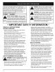
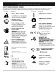
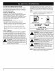
Thepurposeof safetysymbolsisto attractyour attentionto possibledangers.Thesafetysymbols,and theirexplanations, deserveyourcarefulattentionand understanding. Thesafetywarningsdo notby themselves eliminateanydanger.Theinstructions or warningstheygivearenotsubstitute s forproper accidentprevention measures. SYMBOL MEANING SAFETY ALERT SYMBOL: Indicates danger, warning, or caution. Attention is required in order to avoid serious personal injury. May be used in conjunction with other symbols or pictographs.
• Use the unit only in daylight or good artificial light. • Keep outside surfaces free from oil and fuel. • Avoid accidental whenever pulling unit must be in a Starting/Stopping starting. Be in the starting position the starter rope. The operator and stable position while starting. See Instructions. • Do not set unit on any surface except a clean, hard area while engine is running. Debris such as gravel, sand, dust, grass, etc.
SAFETY AND INTERNATIONAL SYMBOLS This operator's manual describes safety and international symbols and pictographs that may appear on this product. Read the operator's manual for complete safety, assembly, operating and maintenance and repair information. SYMBOL MEANING SYMBOL MEANING • ON/OFF ON / START / RUN Indicates danger, warning, or caution. May be used in conjunction with other symbols or pictographs.
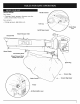
APPLICATION Throttle Control As a blower; • Cleaning of yards, garages, driveways, porches, patios, around walls, fences, etc. As a vacuum; • Picking up leaves, light debris, etc. Fuel Cap J Starter Rope Grip On/Off Stoic Blower/Vacuum Tube Vacuum Inlet Blower Outlet Vacuum Bag \ Blower/Vacuum Mode Change-Over Lever _ _ / \ \ N / / / / \ Choke j/ \_JY " _. Cont _ml__ \ \ \ Spark Plug , , \ \ / _ / ) Vacuum Bag Vacuum Bag Zipper Primer Air filter/muffler cover 7
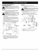
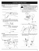
ATTACHING AND REMOVING BLOWER/VACUUM TUBE THE the blower/vacuum tube and vacuum bag mustl ,_WARNING: To avoid serious personal injury, 1 be used when operating this unit J Attaching NOTE: The Blower/Vacuum Tube comes unassembled on this unit. Installation is required to provide safe and easy use for the operator. stop the engine and allow the impeller to stop I WARNING: To prevent serious personal injury, 1 , before attaching or removing tubes. J _11 1.
ATTACHINGAND REMOVING THE VACUUM BAG Attaching 1. Attach the vacuum bag to the vacuum bag hook on the blower/vacuum tube (Fig. 3) INSTALLING _b THE HARNESS never attemptTo to start serious the unitpersonal when standing WARNING: avoid injury, II and the unit clipped to the shoulder strap. I Always follow the starting procedures as described in the Operation section. 1. Push the strap through the center of the buckle. 2. Pull the strap over the cross bar and down through the slot in the buckle (Fig.
OIL AND FUEL MIXING INSTRUCTIONS Old and/or improperly mixed fuel are the main reasons for the unit not running properly. Be sure to use fresh, clean unleaded fuel. Follow the instructions carefully for the proper fuel/oil mixture. Definition of Blended Fuels Today's fuels are often a blend of gasoline and oxygenates such as ethanol, methanol or MTBE (ether). Alcohol-blended fuel absorbs water. As little as 1% water in the fuel can make fuel and oil separate. It forms acids when stored.
STARTING INSTRUCTIONS WARNING: Avoid accidental starting. Be in the starting position whenever pulling the starter rope. The operator and unit must be in a stable position while starting. Position (C) (B) Full Choke Position (A) Also, Do not set unit on any surface except a clean, hard area while starting. Debris such as gravel, sand, dust, grass, etc.
NOTE: If the engine floods while trying to start, place the choke control in the RUN (C IH) position. Move the throttle control to the fast position ( _ ) (Fig 9). Pull the starter rope briskly. The engine should start with three (3) to eight (8) pulls. NOTE: Choking is unnecessary when starting a warm engine. Put the throttle control in the fast position ( _ ) (Fig lO).and start unit with the choke control in the PARTIAL (B I"1) position (Fig. 10).
OPERATING AS A BLOWER 1. Start engine. See Starting/Stopping 2. Set the blower/vacuum mode change-over lever to the up position (Blower Mode) (Fig. 13). Instructions. Use the blower around buildings and for other normal cleaning (Fig. 15). NOTE: Never use the unit with the lever in the halfway position. Fig. 15 Use the blower for walls, overhangs and screens (Fig. 16). Fig. 13 3.
OPERATINGAS A VACUUM 1. Start engine. See Starting/Stopping 2. Set the blower/vacuum mode change-over lever to the down position (Vacuum Mode) (Fig. 17). WARNING: As a vacuum, the unit is designed to pick up dry material such as leaves, grass, small twigs and bits of paper. To avoid serious personal injury, do not attempt to vacuum wet debris and/or standing water as this may result in damage to the Blower/Vacuum. To avoid severe damage to the impeller, do not vacuum metal, broken glass, etc.
L EMPTY THE VACUUM BAG \ WARNING: To avoid serious personal injury, never unzip or remove the vacuum bag without first turning the unit off. tabs PRESS IN NOTE: Empty the bag after each use to avoid deterioration and obstructing air flow, which will reduce the performance of the vacuum. I,_ \ mask when emptying the vacuum bag. ARNING: Wear eye protection and a dust 3. 1. While pressing the latching tabs on both sides of the vacuum bag tube, pull the vacuum bag down off the unit (Fig. 19). 2.
AIR FILTER MAINTENANCE Removing the Air Filter/Muffler _h 1. 3. Cover Wash the filter in detergent and water (Fig. 22). Rinse the filter thoroughly. Squeeze out excess water. Allow it to dry completely. always turn the unit off and allow it to cool before ARNING: To avoid serious personal injury, ,you clean or perform any maintenance on it. Place the choke control in the PARTIAL choke position (B). NOTE: The choke control must be in the PARTIAL choke position (B) (Fig.
SPARK ARRESTOR MAINTENANCE 7. 1. Remove air filter/muffler cover. See Removing the Air Filter/Muffler Cover. 2. Locate muffler front and the two (2) bolts securing it to the engine. (Fig. 25). Remove the two (2) bolts using a fiatblade screwdriver or 5/16-inch socket or nut driver. Pull muffler off of the engine. Place exhaust gasket against muffler's back side. Align exhaust gasket bolt holes with bolt holes in muffler. While holding exhaust gasket in place, insert bolts into muffler's front side.
CARBURETOR SETTING Idle Speed Adjuster The idle speed adjuster of the engine is adjustable though the Air filter/muffler cover (Fig 27). NOTE: Careless adjustments can seriously damage your unit. An authorized service dealer should make carburetor adjustments. Check Fuel Mixture Old and/or improperly mixed fuel is usually the reason for the unit not running properly. Drain and refill the tank with fresh, properly mixed fuel prior to making any adjustments.
CLEANING THE UNIT STORAGE Store the unit indoors, away from moisture and harmful substances such as fertilizers and solvents. injury, always turn the unit off and allow it to ARNING: cool before clean or perform any TOyou avoid serious personal maintenance on it. I,_ Never store the unit with petrol (gasoline) in the tank where fumes may reach an open flame or spark. Allow the engine to cool before storing.
CAUSE ACTION Empty fuel tank Fill fuel tank Primer bulb wasn't pressed enough Press primer bulb fully and slowly 5-7 times Engine flooded Use starting procedure with choke control in the RUN position, Pg.
Engine Type Displacement ................................................................. ............................................................................ Operating RPM ................................................................. Idle Speed RPM ................................................................. Ignition Type ......................................................................... On/Off Stop Control ...................................................... Spark Plug Gap ...
EPA Emission Control Warranty Statement Your Warranty Rights and Obligations The Environmental Protection Agency and MTD SOUTHWEST INC (MTD) are pleased to explain the emission control system warranty on your 2002 and later small off-road engine. New small off-road engines must be designed, built and equipped to meet stringent anti-smog standards.
MANUFACTURER'S LIMITED WARRANTY FOR: ® The limited warranty set forth below is given by MTD SOUTHWEST INC ("MTD") with respect with new merchandise purchased and used in the United States, its possessions and territories. MTD warrants this product against defects in material and workmanship for a period of two (2)years commencing on the date of original purchase and will, at its option, repair or replace, free of charge, any part found to be defective in material or workmanship.