
Manual

ATTACHING AND REMOVING THE
BLOWER/VACUUM TUBE
,_WARNING: To avoid serious personal injury, 1
the blower/vacuum tube and vacuum bag mustl
be used when operating this unit J
Attaching
NOTE: The Blower/Vacuum Tube comes unassembled
on this unit. Installation is required to provide
safe and easy use for the operator.
_11 WARNING: To prevent serious personal injury, 1
stop the engine and allow the impeller to stop I
,before attaching or removing tubes. J
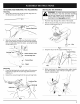
1. Remove the screws and nuts provided from the
hardware pack.
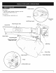
2. Insert the blower/vacuum tube all the way into the
opening on the motor housing until the holes in the
tabs on the blower/vacuum tube align with the screw
holes in the housing (Fig. 1).
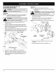
3. Insert the 2 (two) 8-32 x 3/4" slotted T20 Torx screws
into the right side of the motor housing and the 2 (two)
nuts into the left side of the motor housing (Fig. 2).
Motor Housing
_ 4_ -_ Nut
Blower/Vacuum
Tube
Removing
NOTE: It may be necessary to remove the
Blower/Vacuum Tube to clear a blocked tube
or impeller.
_ ARNING: To prevent serious personal injury, I
stop the engine and allow the impeller to stop
before attach ng or remov ng tubes.
1. Remove the 2 (two) self-tapping screws from either
side of the housing.
2. Remove the 2 (two) screws and nuts holding the
blower/vacuum tube on the housing (Fig. 2).
NOTE: Keep the hardware in a safe place for future use.
/
Screw Self Tapping
and Nut Screw
Screw and Nut /
Fig. 2
3. Remove the blower/vacuum tube from the motor
housing.
4. Replace Blower/Vacuum Tube before use.
Screw
Self-Tapping Screw _.
Fig. 1
4. Tighten the screws firmly. Do not over-tighten.
5. Install the 2 (two) remaining self-tapping 8-16 x 3/4"
slotted T20 Torx screws into the holes on either side
of the housing (Fig. 2). Tighten until snug, do not
over-tic hten.
8