OPERATOR’S MANUAL 10 in. Compound Miter Saw TS1342 - Double Insulated Your miter saw has been engineered and manufactured to our high standard for dependability, ease of operation, and operator safety. When properly cared for, it will give you years of rugged, trouble-free performance. WARNING: To reduce the risk of injury, the user must read and understand the operator’s manual before using this product. Thank you for your purchase.
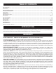
TABLE OF CONTENTS � � � � � � � � � � � � � Introduction ..................................................................................................................................................................... 2 Warranty .......................................................................................................................................................................... 2 General Safety Rules .....................................................
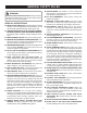
GENERAL SAFETY RULES SECURE WORK. Use clamps or a vise to hold work when practical, it is safer than using your hand and frees both hands to operate the tool. WARNING: Read and understand all instructions. Failure to follow all instructions listed below, may result in electric shock, fire and/or serious personal injury. DO NOT OVERREACH. Keep proper footing and balance at all times. MAINTAIN TOOLS WITH CARE. Keep tools sharp and clean for better and safer performance.
GENERAL SAFETY RULES USE ONLY CORRECT BLADES. Do not use blades with incorrect size holes. Never use blade washers or blade bolts that are defective or incorrect. The maximum blade capacity of your saw is 10 in. BEFORE MAKING A CUT, BE SURE ALL ADJUSTMENTS ARE SECURE. BE SURE BLADE PATH IS FREE OF NAILS. Inspect for and remove all nails from lumber before cutting. NEVER TOUCH BLADE or other moving parts during use. NEVER START A TOOL WHEN ANY ROTATING COMPONENT IS IN CONTACT WITH THE WORKPIECE.
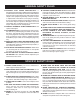
SPECIFIC SAFETY RULES NEVER reach behind, under, or within three inches of the blade and its cutting path with hands and fingers for any reason. MAKE SURE THE WORK AREA HAS AMPLE LIGHTING to see the work and that no obstructions will interfere with safe operation BEFORE performing any work using the saw. NEVER reach to pick up a workpiece, a piece of scrap, or anything else that is in or near the cutting path of the blade.
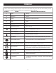
SYMBOLS Some of the following symbols may be used on this tool. Please study them and learn their meaning. Proper interpretation of these symbols will allow you to operate the tool better and safer.
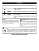
SYMBOLS The following signal words and meanings are intended to explain the levels of risk associated with this product. SYMBOL SIGNAL MEANING DANGER: Indicates an imminently hazardous situation, which, if not avoided, will result in death or serious injury. WARNING: Indicates a potentially hazardous situation, which, if not avoided, could result in death or serious injury. CAUTION: Indicates a potentially hazardous situation, which, if not avoided, may result in minor or moderate injury.
ELECTRICAL DOUBLE INSULATION EXTENSION CORDS Double insulation is a concept in safety in electric power tools, which eliminates the need for the usual threewire grounded power cord. All exposed metal parts are isolated from the internal metal motor components with protecting insulation. Double insulated tools do not need to be grounded. When using a power tool at a considerable distance from a power source, be sure to use an extension cord that has the capacity to handle the current the tool will draw.
GLOSSARY OF TERMS Non-Through Cuts Any cutting operation where the blade does not extend completely through the thickness of the workpiece. Anti-Kickback Pawls (radial arm and table saws) A device which, when properly installed and maintained, is designed to stop the workpiece from being kicked back toward the front of the saw during a ripping operation. Arbor The shaft on which a blade or cutting tool is mounted.
FEATURES PRODUCT SPECIFICATIONS Blade Arbor .............................................................. 5/8 in. Cutting Capacity with Miter at 0°/Bevel 0°: Maximum nominal lumber sizes: ................. 2 x 6, 4 x 4 Blade Diameter .......................................................... 10 in. Cutting Capacity with Miter at 45°/Bevel 0°: Maximum nominal lumber sizes: ...........................2 x 4 No Load Speed .................................... 5,500 r/min. (RPM) Input .......................
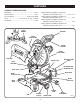
FEATURES KNOW YOUR COMPOUND MITER SAW See Figure 1. The safe use of this product requires an understanding of the information on the tool and in this operator’s manual as well as a knowledge of the project you are attempting. Before use of this product, familiarize yourself with all operating features and safety rules. CARRYING HANDLE SAW ARM 15 AMP MOTOR The saw has a powerful 15 amp motor with sufficient power to handle tough cutting jobs.
FEATURES POSITIVE STOPS ON MITER TABLE MITER FENCE Positive stops have been provided at 0 , 15 , 22-1/2 , 30 , and 45°. The 22-1/2° and 45° positive stops have been provided on both the left and right side of the miter table. ° ° ° The miter fence on the compound miter saw has been provided to hold the workpiece securely against when making all cuts. The left side is also larger providing additional support.
LOOSE PARTS The following items are included with the tool: Miter Lock Handle Blade Wrench Dust Bag Operator’s Manual Work Clamp DUST BAG MITER LOCK HANDLE WORK CLAMP BLADE WRENCH Fig. 6 WARNING: The use of attachments or accessories not listed might be hazardous and could cause serious personal injury.
ASSEMBLY UNPACKING WARNING: This product requires assembly. Carefully lift saw from the carton by the carrying handle and the saw base, and place it on a level work surface. NOTE: This tool is heavy. To avoid back injury, lift with your legs, not your back, and get help when needed. This saw has been shipped with the saw arm secured in the down position. To release the saw arm, push down on the top of the saw arm, cut the tie-wrap, and pull out on the lock pin. Lift the saw arm by the handle.
ASSEMBLY MITER LOCK HANDLE MITER LOCK HANDLE See Figure 8. To install the miter lock handle, place the threaded stud on the end of the miter lock handle into the threaded hole in the control arm. Turn clockwise to tighten. TO TIGHTEN DUST BAG See Figure 9. A dust bag is provided for use on the miter saw. It fits over the exhaust port on the upper blade guard. To install it, remove dust guide from exhaust port.
ASSEMBLY TO INSTALL / REPLACE THE BLADE See Figures 11 - 12. WARNING: SPINDLE LOCK BUTTON A 10 in. blade is the maximum blade capacity of the saw. Never use a blade that is too thick to allow outer blade washer to engage with the flats on the spindle. Larger blades will come in contact with the blade guards, while thicker blades will prevent the blade bolt from securing the blade on the spindle. Either of these situations could result in a serious accident and can cause serious personal injury.
ASSEMBLY FRAMING SQUARE WARNING: Make sure the spindle lock button is not engaged before reconnecting saw into power source. Never engage spindle lock button when blade is rotating. MITER FENCE MITER TABLE NOTE: Many of the illustrations in this manual show only portions of the compound miter saw. This is intentional so that we can clearly show points being made in the illustrations. Never operate the saw without all guards securely in place and in good operating condition.
ASSEMBLY SQUARING THE SAW BLADE TO THE FENCE See Figures 16 - 20 Unplug the saw. Pull the saw arm all the way down and engage the lock pin to hold the saw arm in transport position. Loosen the miter lock handle approximately one-half turn. Depress the miter lock plate and rotate the miter table until the pointer on the control arm is positioned at 0°. Release the miter lock plate and securely tighten the miter lock handle. Lay a framing square flat on the miter table.
ASSEMBLY SQUARING THE BLADE TO THE MITER TABLE See Figures 21 - 23. Unplug the saw. BEVEL LOCK KNOB Pull the saw arm all the way down and engage the lock pin to hold the saw arm in transport position. MITER FENCE BLADE Loosen the miter lock handle approximately one-half turn. MITER LOCK PLATE Depress the miter lock plate and rotate the miter table until the pointer on the control arm is positioned at 0°. Release the miter lock plate and securely tighten the miter lock handle.
OPERATION CUTTING WITH YOUR COMPOUND MITER SAW WARNING: Do not allow familiarity with tools to make you careless. Remember that a careless fraction of a second is sufficient to inflict serious injury. WARNING: When using a work clamp or C-clamp to secure the workpiece, clamp workpiece on one side of the blade only. The workpiece must remain free on one side of the blade to prevent the blade from binding in workpiece. The workpiece binding the blade will cause motor stalling and kickback.
OPERATION Loosen the bevel lock knob and move the saw arm to the left to the desired bevel angle. Bevel angles can be set from 0° to 45°. Align the indicator point for the desired angle. Once the saw arm has been set at the desired angle, securely tighten the bevel lock knob. Rotate the control arm until the pointer aligns with the desired angle on the miter scale. Release the miter lock plate.
OPERATION Grasp the stock firmly with one hand and secure it against the fence. Use the optional work clamp or a C-clamp to secure the workpiece when possible. See Figure 26. COMPOUND MITER CUT Before turning on the saw, perform a dry run of the cutting operation just to make sure that no problems will occur when the cut is made. Grasp the saw handle firmly then squeeze the switch trigger. Allow several seconds for the blade to reach maximum speed.
OPERATION Grasp the stock firmly with one hand and secure it against the fence. Use the optional work clamp or a C-clamp to secure the workpiece when possible. Before turning on the saw, perform a dry run of the cutting operation just to make sure that no problems will occur when the cut is made. Grasp the saw handle firmly then squeeze the switch trigger. Allow several seconds for the blade to reach maximum speed. Slowly lower the blade into and through the workpiece.
OPERATION CUTTING COMPOUND MITERS To aid in making the correct settings, the compound angle setting chart below has been provided. Since compound cuts are the most difficult to accurately obtain, trial cuts should be made in scrap material, and much thought and planning made, prior to making the required cut. PITCH OF SIDE 0° 5° 10° 15° 20° 25° 30° 35° 40° 45° 50° NUMBER OF SIDES 4 5 6 7 8 M- 45.00° B- 0.00° M- 44.89° B- 3.53° M- 44.56° B- 7.05° M- 44.01° B- 10.55° M- 36.00° B- 0.00° M- 30.00° B- 0.
OPERATION CUTTING CROWN MOLDING When setting the bevel and miter angles for compound miters, remember that the settings are interdependent; changing one angle changes the other angle as well. Keep in mind that the angles for crown moldings are very precise and difficult to set. Since it is very easy for these angles to shift, all settings should first be tested on scrap molding. Also most walls do not have angles of exactly 90°, therefore, you will need to fine tune your settings.
OPERATION Bevel Angle Setting 33.85 ° Type of Cut Left side, inside corner 1. Top edge of molding against fence 2. Miter table set right 31.62° 3. Save left end of cut 33.85° Right side, inside corner 1. Bottom edge of molding against fence 2. Miter table set left 31.62° 3. Save left end of cut 33.85° Left side, outside corner 1. Bottom edge of molding against fence 2. Miter table set left 31.62° 3. Save right end of cut 33.85° Right side, outside corner 1. Top edge of molding against fence 2.
ADJUSTMENTS DEPTH STOP ADJUSTMENTS WARNING: See Figure 34. Unplug the saw. Before performing any adjustment, make sure the tool is unplugged from the power supply. Failure to heed this warning could result in serious personal injury. To adjust the depth stop use a 10 mm wrench and loosen the hex nut located on the side of the miter saw housing. The compound miter saw has been adjusted at the factory for making very accurate cuts.
ADJUSTMENTS POSITIVE STOP ADJUSTMENTS Square the blade to the miter table as described in the Assembly section of this manual. Retighten bevel lock knob. Next, retighten lock nut securing the positive stop adjustment screw. Recheck blade-to-table alignment. NOTE: The above procedure can be used to check blade squareness of the saw blade to the miter table at both 0° and 45° angles. The saw has two scale indicators, one on the bevel scale and one on the miter scale.
NOTES 29
OPERATOR’S MANUAL 10 in. Compound Miter Saw TS1342 - Double Insulated WARNING: Some dust created by power sanding, sawing, grinding, drilling, and other construction activities contains chemicals known to cause cancer, birth defects or other reproductive harm. Some examples of these chemicals are: • lead from lead-based paints, • crystalline silica from bricks and cement and other masonry products, and • arsenic and chromium from chemically-treated lumber.