
Parts List/Tune Up Info
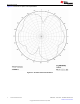

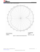


Table Of Contents

2.3 Bandwidth
Another way of measuring the bandwidth after the antenna is implemented on a PCB and connected to a
transmitter is to write test software that steps a carrier across the frequency band of interest. By using the
maximum hold function on a spectrum analyzer, the variation in output power across frequency can easily be
measured.
Figure 2-9 shows how the output power varies on the IFA when the PCB is horizontally oriented and the
receiving antenna has horizontal polarization. This measurement was not performed in an anechoic chamber,
thus the graph shows only the relative variation for the given frequency band.
Figure 2-9. Bandwidth of IFA
3 Summary
The PCB antenna presented in this document performs well for all frequencies in the 2.4-GHz ISM band. Except
for two narrow dips, the antenna has an omni directional radiation pattern in the plane of the PCB. These
properties will ensure stable performance regardless of operating frequency and positioning of the antenna.
Table 3-1 lists the most important properties for the IFA.
Table 3-1. Summary of IFA Properties
Gain in XY plane 1.1 dBi
Gain in XZ plane 3.3 dBi
Gain in YZ plane 1.6 dBi
Reflection < –15 dB
Antenna size 25.7 × 7.5 mm
4 References
1. CC2430DB Reference Design
www.ti.com Measurement Results
SWRU120D – APRIL 2007 – REVISED JANUARY 2019
Submit Document Feedback
2.4-GHz Inverted F Antenna 11
Copyright © 2021 Texas Instruments Incorporated