
Parts List/Tune Up Info
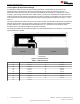
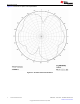
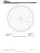

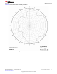
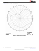
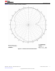

Table Of Contents

2 Measurement Results
All of the results presented in this section are based on measurements performed with the CC2430DB [1]
evaluation board.
2.1 Radiation Pattern
Figure 2-1 shows how to relate all of the radiation patterns to the orientation of the antenna. The radiation
patterns were measured with the CC2430 device programmed to 0-dBm output power.
Figure 2-1. Relating Antenna to Radiation Patterns
www.ti.com Measurement Results
SWRU120D – APRIL 2007 – REVISED JANUARY 2019
Submit Document Feedback
2.4-GHz Inverted F Antenna 3
Copyright © 2021 Texas Instruments Incorporated