WTS Wireless Target System (WTS) Table of Contents 1 General. . . . . . . . . . . . . . . . . . . . . . . . . . . . . . . . . . . . . . . . . . 1.1 Preface . . . . . . . . . . . . . . . . . . . . . . . . . . . . . . . . . . . . . . 1.2 Safety Instructions. . . . . . . . . . . . . . . . . . . . . . . . . . . . . . 1.2.1 Attentions general . . . . . . . . . . . . . . . . . . . . . . . . 1.2.2 Laser safety . . . . . . . . . . . . . . . . . . . . . . . . . . . . 1.2.3 Battery safety . . . . . . . . . . . . .
WTS 4 Installation . . . . . . . . . . . . . . . . . . . . . . . . . . . . . . . . . . . . . . . 21 4.1 WCU installation . . . . . . . . . . . . . . . . . . . . . . . . . . . . . . . 21 4.2 Antenna installation . . . . . . . . . . . . . . . . . . . . . . . . . . . . . 22 4.3 WDU installation . . . . . . . . . . . . . . . . . . . . . . . . . . . . . . . 24 4.3.1 Change WDU battery. . . . . . . . . . . . . . . . . . . . . . 27 4.3.2 FCC and User Information. . . . . . . . . . . . . . . . . . . . 28 4.
1 WTS 1 General 1.1 Preface This manual describes the use of the Wireless Target System (WTS) for vehicles and objects. The manual is intended for instructors, who take part in the simulation exercise. The equipment is distributed by Saab Training Systems. 1.2 Safety Instructions Attentions called WARNING! or CAUTION! are included in all procedures which can cause injury to personnel or damage to the equipment.
WTS 1.2.2 Laser safety The laser used in the simulation equipment is classified as laser class 1 (eye safe), according to IEC 60825-1. It is possible to observe the laser at zero distance, without and with optics (binoculars) without any risk of injury. 1.2.
1 WTS 1.
WTS © Saab Training Systems 6 General 8875 801-267
2 WTS 2 Introduction 2.1 Training modes Gunnery mode: The WTS is automatically reactivated 10 seconds after being killed. Combat mode: The WTS is not automatically reactivated after being killed. Tampering kill after startup. Combat alive mode: The WTS is not automatically reactivated after being killed. No tampering kill after startup. 2.2 Hit effects on the target The following effects are possible when a vehicle is hit. All of these events are stored for AAR.
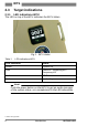
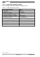
WTS 2.3 Target indications 2.3.1 LED indications WCU The LED on top of the WCU indicates the WCU status. Fig 1. WCU status Table 1. LED indications WCU LED indication Status Green System OK Red Total Kill / Tampering Kill / Temporary Kill Yellow BIT Error Yellow Low battery Note! Push the power button on the WCU to get an audio message of the system status, as a complement to the LED indications.
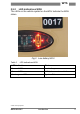
2 WTS 2.3.2 LED indications WDU The LEDs on the vehicle symbol on the WDU indicate the WDU status. Fig 2. Low battery WDU Table 2.
WTS 2.3.3 Strobe light indications WDU The strobe light on the WDU indicate the target events. Table 3.
2 WTS 2.3.4 Audio messages and sound effects The audio messages and sound effects are given at the detection of the event. The status of the player is also repeated 20 seconds after the event. Table 4.
WTS 2.4 WTS description The WTS system consists of a Wireless Central Unit (WCU) and Wireless Detector Units (WDU). Inside the WCU there is a Computer Unit and a Power Unit. Each WDU has 1 detector and 1 strobe hit indicator. The WDU can also be equipped with 2 reflectors. The WTS is powered by standard PDD batteries. Fig 3.
2 WTS Note! See the Table of Contents in the storage box for the exact contents of the WTS kit. When a vehicle is hit, the strobe on the WDU will flash. Soldiers inside a vehicle wearing Personnel Detection Devices (PDD) will be affected through Wireless Local Network (WLN) radio when the vehicle is hit and damaged. The vulnerability type is set in the system by using a Control Gun (CGUN), see 5.5 Change protection level. The WTS has three protection levels: • Low • Medium • High 2.4.
WTS 2.4.2 WDU description The WDU is slave to the WCU in the WTS. It is used for detection of laser from firing systems. Fig 5.
2 WTS Fig 6.
WTS 2.4.3 Loudspeaker overview The loudspeaker gives the players in the target sound effects and informative messages about status, hit events and errors. Fig 7. Loudspeaker 2.4.4 DAN description This network is used to distribute messages between EXCON and the players in the field. The information that is sent over the DAN includes these data: • AWES event data • Player and exercise control messages • Differential corrections for the MSA • Network management messages.
2 WTS 2.4.5 MSA description The Miniaturized Smart Antenna (MSA) is a GPS antenna enclosed in a plastic housing. It receives the time and position data from the GPS, which is used to determine the position of the vehicle. Fig 8.
WTS 2.4.6 IBU/VAD description The IBU/VAD is installed inside the vehicle. The IBU/VAD is powered by a internal battery. Fig 9. IBU/VAD The IBU/VAD sends IR signals to the soldiers with PDDs inside the vehicle. The result is that the PDDs start the communication with the WTS on the vehicle. The WTS then sends a message to EXCON that there are PDDs in the vehicle. If the vehicle is hit, the target system calculates the effect for the vehicle and send the result to the PDDs.
3 WTS 3 Technical Data 3.1 Environmental Conditions Table 5. Environmental Conditions Variable Value Humidity Rainproof Operating temperature -25°C to +40°C (-13°F to +104°F) Storage temperature -34°C to +62°C (-29°F to +143°F) 3.2 Weights and dimensions Table 6. Weights and dimensions Unit Length mm (inches) Width mm (inches) Height mm (inches) Weight kg (lb) Battery 1-cell 70 (2.8) 60 (2.4) 20 (0.8) 0.19 (0.42) Battery 2-cell 145 (5.7) 60 (2.4) 20 (0.8) 0.30 (0.
WTS 3.3 Batteries Table 7. Operational time WCU Battery With DAN Without DAN WCU 1 cell battery 1 day 1,5 days WCU 2 cell battery 2 days 3 days Table 8. Operational time WDU WDU Table 9.
4 WTS 4 Installation 4.1 WCU installation 4.1.1 Open the WCU. Position two 1 cell batteries or one 2 cell battery in the holder. Push them down until they are locked in the holder (click). Fig 10. Battery installation WCU Close the WCU. 4.1.2 Install the WCU. There are two alternatives for placement of the WCU: External installation (centralized antenna installation) 1 Place the WCU on the roof of the vehicle. 2 Secure the unit with ratchet belts.
WTS 4.2 Antenna installation There are two alternatives for installation of the antennas. • Centralized installation for when the WCU has been installed externally. • Spread out installation for when the WCU has been installed internally. Centralized installation 1 Place the antennas on the magnetic area on top of the WCU. 2 Connect the cables to the WCU, see 4.5 Cable installation. 3 Strap any excess cable length to the ratchet belts that hold the WCU in place. Fig 11.
4 WTS Fig 12. Install antennas 1. MSA 3. DAN antenna 2. WLN antenna (inside vehicle) 4. WLN antenna CAUTION! Make sure the cables will not be damaged during installation. CAUTION! Make sure the cables are properly secured before transportation. Note! A large or armoured vehicle may require both WLN antennas on the outside of the vehicle.
WTS 4.3 WDU installation 1. Lift the rubber cover on the WDU and push down the battery. Fig 13. Battery installation WDU 2. Put the rubber cover back on. Make sure it seals tight on the back of the WDU. 3. A green LED indicates that the battery is OK. 4. Push the button and check the vehicle symbol on the WDU. A red LED will indicate where on the vehicle the WDU should be installed - front, rear, left or right. Fig 14.
4 WTS 5. Install the WDUs with Velcro on a clean, flat surface on each side of the vehicle. Fig 15. Install WDUs Fig 16. Install WDUs, truck CAUTION! If the Velcro becomes clogged with mud, clean the Velcro as soon as possible. The WDU may become detached from the Velcro.
WTS Note! The WDUs and the antennas send signals back and forth. In order for this to work, the path between the WDUs and the antennas must not be blocked and they must be in reach of each other. Move the WDUs higher up on the vehicle if necessary. Note! A maximum of 10 WDUs can be installed on each vehicle or target (i.e. max 10 WDU can be associated to a WCU). 6. Secure the WDUs with straps. Fig 17.
4 WTS 4.3.1 Change WDU battery 1. Lift the rubber cover on the WDU and lift the battery out. Fig 18. Remove battery WDU Note! Make sure to push on both corners of the battery, not in the middle. 2. Replace the battery and put the rubber cover back on. Make sure it seals tight on the back of the WDU. 3. A green LED indicates that the battery is OK.
4 WTS 4.3.2 Regulatory Statement Note! The following Statement and Information refers to the WDU ONLY. FCC Certification The United States Federal Communication Commission (FCC) has established certain rules governing the use of electronic equipment. Part15, Class B 1. This device is FCC Certified FCC ID: R4AWDU24A 2. This device complies with Part 15 of FCC rules.
WTS 4.4 IBU/VAD and loudspeaker installation 1. Install the IBU/VAD and the loudspeaker with Velcro. Fig 19. IBU/VAD and loudspeaker installation Note! Make sure the IBUs/VADs can send IR light to the PDDs inside the vehicle. Note! Because of different design of the vehicles the inside might look different.
4 WTS 4.5 Cable installation 1. Connect the cables to the WCU. Fig 20.
WTS 2. Make sure to tighten the cable connectors until the red mark on the connector is not visible. Fig 21. Red mark not visible 3. Connect the power cable to the vehicle power outlet (optional). Fig 22. Power outlet Note! There are several options for power supply depending on vehicle type. When the power cable is connected, the batteries in the WCU will be charged.
4 WTS © Saab Training Systems 32 Installation 8875 801-267
5 WTS 5 Operation 5.1 Start up 1. Push the power button on the WCU and hold for 2 seconds. A green LED will indicate that the WCU is turned on. Note! If the system is in Tampering Kill mode after power up, select the command RESET on the CGUN. Aim at a WDU and fire the CGUN to reset the system. 5.1.1 First time procedure The very first time the system is used, you may want to make sure the WDUs are properly associated to the WCU. 1 Select the command TEST on the CGUN and fire at the WDU.
WTS 5.3 WDU association Note! This procedure is only necessary if a WDU has been removed from the system or if extra WDUs need to be added to the system. A maximum of 10 WDUs can be used on one vehicle. 1 Push in the center of the button on the WDU and hold until a red LED is lit next to the vehicle symbol. Fig 23. Push the WDU button Fig 24.
5 WTS 2 Push the button to move the LED around the vehicle symbol to select where the WDU is installed. 3 When a WDU position is selected, wait until the LEDs are turned off to save the selection. 4 Hold the WDU above the WCU and push the button on the WDU once. Make sure the WDU can send IR light to the WCU. Fig 25. WDU association 5 The system will generate the audio message ASSOCIATED + ID NUMBER. 6 Repeat for each WDU.
WTS 5.4 Test 1. Push the button once on the WCU to test the system. Make sure the system generates the audio message SYSTEM OK. Note! It is also possible to select the command TEST on the CGUN and fire to test the system. It is possible to change the protection level, see 5.5 Change protection level for more information. 2. Push the button twice on the WCU to get information about the ID for the system, armor level (e.g. ID 11, high, System OK), OID, PSID and if the system is connected to EXCON. 5.
5 WTS 5.6 Power down 1. Push and hold the power button on the WCU for 3 seconds. The audio message SYSTEM POWER DOWN will be heard. Or open the WCU, remove the batteries and close the WCU.
WTS 38 Operation 8875 801-267
6 WTS 6 Removal 6.1 Remove WDU from system 1. Hold the WDU above the WCU and push the button on the WDU once. Make sure the WDU can send IR light to the WCU. Fig 26. WDU removal 6.2 Remove all WDUs from system 1. For OSAG: Select the commands ACCESS + ACCESS + RESET on the CGUN. Aim at the target system and fire the CGUN to remove all WDUs from the system. 2. For MILES: Select the commands CTRL + CTRL + RESET on the CGUN.
WTS © Saab Training Systems 40 Removal 8875 801-267
7 WTS 7 Troubleshooting 7.1 Troubleshooting Check that all cables are connected properly. Push the button on the WCU to test the system. Listen for error messages from the loudspeaker. Table 10. Troubleshooting Symptom Cause Corrective action WDU missing. Battery empty. Change battery. WDU not associated to WCU. Associate the WDU to the WCU. WDU in "sleep mode". Push the power button on the WDU. Low battery. Change battery. Antennas out of reach.
WTS Symptom Cause Corrective action Yellow LED lit on the WCU. BIT error. Push the power button on the WCU to play a BIT error audio message. Low battery. Push the power button on the WCU to play an audio message about which WDU needs a new battery.
8 WTS 8 Maintenance 8.1 Cleaning 1. Remove mud and dust with a nylon brush. 2. Clean all exterior parts with a wet sponge. 3. Clean all optical surfaces with lens cleaning paper. If necessary use detergent without citric acid e.g. windshield wiper fluid. Clean the glass smoothly with circular movements from the centre to the edge. 4. Dry all equipment with a dry cloth.
WTS © Saab Training Systems 44 Maintenance 8875 801-267
A WTS Appendix A List of Figures Fig 1. WCU status . . . . . . . . . . . . . . . . . . . . . . . . . . . . . . . . . . . Fig 2. Low battery WDU . . . . . . . . . . . . . . . . . . . . . . . . . . . . . . . Fig 3. WTS overview . . . . . . . . . . . . . . . . . . . . . . . . . . . . . . . . . Fig 4. WCU overview . . . . . . . . . . . . . . . . . . . . . . . . . . . . . . . . . Fig 5. WDU overview, with reflectors . . . . . . . . . . . . . . . . . . . . . Fig 6. WDU overview, without reflectors . . . . . . .
WTS Table 9. Power cable (optional) . . . . . . . . . . . . . . . . . . . . . . . . . . Table 10. Troubleshooting . . . . . . . . . . . . . . . . . . . . . . . . . . . . . .
I WTS Index A Abbreviations 1.3 Abbreviations. . . . . . . . . . . . . . . . . . . . . . . . . . . . . . . . . . Armor 5.5 Change protection level. . . . . . . . . . . . . . . . . . . . . . . . . . Audio messages 2.3.4 Audio messages and sound effects . . . . . . . . . . . . . . . 5 36 11 B Ballistic simulation 5.2.1 Ballistic (BT46) simulation . . . . . . . . . . . . . . . . . . . . . . Battery safety 1.2.3 Battery safety . . . . . . . . . . . . . . . . . . . . . . . . . . . . . . . .
WTS F First time procedure 5.1.1 First time procedure . . . . . . . . . . . . . . . . . . . . . . . . . . . 4.3.2 FCC Information . . . . . . . . . . . . . . . . . . . . . . . . . . . 33 28 G General 1.2.4 General . . . . . . . . . . . . . . . . . . . . . . . . . . . . . . . . . . . . . 4 H Hit effect 2.2 Hit effects on the target . . . . . . . . . . . . . . . . . . . . . . . . . . Humidity 3.1 Environmental Conditions . . . . . . . . . . . . . . . . . . . . . . . . 7 19 I Ibu 2.4.
I WTS Miniaturized smart antenna Msa 2.4.5 MSA description . . . . . . . . . . . . . . . . . . . . . . . . . . . . . . 17 N Note 1.2.1 Attentions general . . . . . . . . . . . . . . . . . . . . . . . . . . . . 3 O One-way simulation 5.2.2 MILES/One-way simulation . . . . . . . . . . . . . . . . . . . . . Operational time 3.3 Batteries . . . . . . . . . . . . . . . . . . . . . . . . . . . . . . . . . . . . . 33 20 P Power 2.4.7 Power system description . . . . . . . . . . . . . . . . . . . . . .
WTS T Temperature 3.1 Environmental Conditions . . . . . . . . . . . . . . . . . . . . . . . . Test 5.4 Test . . . . . . . . . . . . . . . . . . . . . . . . . . . . . . . . . . . . . . . . . Training modes 2.1 Training modes . . . . . . . . . . . . . . . . . . . . . . . . . . . . . . . . Troubleshooting 7.1 Troubleshooting . . . . . . . . . . . . . . . . . . . . . . . . . . . . . . . . 19 36 7 41 V Vad 2.4.6 IBU/VAD description . . . . . . . . . . . . . . . . . . . . . . . . . . . Vad installation 4.