Saab AB (publ.
R60 Station This page is intentionally left blank R60 User Manual Document Number Version Date 7000 120-019 A1 2022-08-10 Page 2 (98)
R60 Station i COPYRIGHT The entire contents of this manual and its appendices, including any future updates and modifications, shall remain the property of Saab AB (publ.) TransponderTech at all times. The contents must not, whether in its original form or modified, be wholly or partly copied or reproduced, nor used for any other purpose than the subject of this manual. ii DISCLAIMER While reasonable care has been exercised in the preparation of this manual, Saab AB (publ.
R60 Station iv CONTACT INFORMATION For installation, service and technical support please contact your local sales representative. Saab AB (publ.) TransponderTech, SWEDEN Låsblecksgatan 3 SE-589 41 Linköping Sweden Phone: +46 1318 9420 Email: support.transpondertech@saabgroup.com http://saab.
R60 Station CONTENTS 1 INTRODUCTION ..................................................................................................................................................... 10 1.1 1.2 2 DOCUMENT ORIENTATION ............................................................................................................................................... 10 REFERENCES ...................................................................................................................................
R60 Station 5.6.1 5.6.2 5.6.3 5.6.4 5.6.5 6 Information Panel ...................................................................................................................................... 45 Legend panel .............................................................................................................................................. 46 Channels panel .........................................................................................................................................
R60 Station 12.1 AIS BASE STATION STATEMENT OF CONFORMITY ................................................................................................................ 93 12.2 MODULE B CERTIFICATE ................................................................................................................................................. 95 12.3 REACH AND ROHS DECLARATION ...................................................................................................................................
R60 Station LIST OF TABLES TABLE 2-1 – FRONT DISPLAY CONFIGURATION PARAMETERS TABLE 4-1 – LICENSED FEATURES IN THE R60 BASE STATION TABLE 5-1 – DESCRIPTION OF FEATURES MONITORED IN THE ALARMS SUB-CATEGORY TABLE 5-2 – DESCRIPTION OF ALARM INDICATOR ICONS TABLE 5-3 – FEATURED DISPLAY OF THE R60 UNIT STATUS TABLE 6: VDL LINK MAP INFORMATION PANEL FIELDS TABLE 6-1 – GENERAL PARAMETERS TABLE 6-2 – NETWORK PARAMETERS TABLE 6-3 – PARAMETERS FOR INTERFACES TABLE 6-4 – PARAMETERS ON THE GNSS PAGE TABLE 6-5 – PARAMET
R60 Station LIST OF FIGURES FIGURE 2-1: FIGURE 2-2: FIGURE 2-3: FIGURE 3-1: FIGURE 3-2: FIGURE 3-3: FIGURE 3-4: FIGURE 3-5: FIGURE 3-6: FIGURE 3-7: FIGURE 3-8: FIGURE 3-9: FIGURE 3-10: FIGURE 3-11: FIGURE 3-12: FIGURE 3-13: FIGURE 3-14: FRONT DISPLAY MAIN MENU................................................................................................................................... 14 STATISTICS VIEW ....................................................................................................
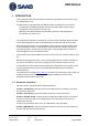
R60 Station 1 INTRODUCTION This manual describes the web-based remote control graphical user interfaces (GUI) for an R60 Station unit. The R60 Station is equipped with two different Ethernet based service interfaces. - Configuration and Monitoring Web Interface (Provides VDES monitoring and configuration functionality see section 3.3) R60 Supervisor Web Interface (Provides R60 supervision and configuration functionality see section 3.
R60 Station Section 5, Monitor, contains information about the alarm and status monitoring functions that are built into the web GUI. Section 6, Configure, contains information about all R60 Station parameters and how to configure them. Section 7, Maintenance, describes how to upgrade the firmware and software of the R60 Station. Section 8, Supervisor Web, describes the specific functions provided by the Supervisor Web GUI of the R60 Station.
R60 Station Ref [7] Maritime navigation and radio communication equipment and systems – Automatic identification systems (AIS) Part 3: Repeater station – Minimum operational and performance requirements, Methods of test and required test results Document number: IEC 62320-3 Ed.1 Ref [8] IALA GUIDELINE G1139 THE TECHNICAL SPECIFICATION OF VDES Edition 1, December 2017 Ref [9] Statement of Conformity Document number: BSH/454.
R60 Station 2 FRONT PANEL 2.1 Power Button The R60 power button is a momentary push button with a built in RGB LED for status indication. The R60 supervisor will always be powered on and accessible while either AC or DC power is available. 2.1.1 Operation To power on the R60, push the button. The R60 station will power on immediately. To power off the R60, push and hold the button depressed for at least 2 seconds. 2.1.
R60 Station The display is a 4.3” colour capacitive touch display. The graphical user interface is navigated by pressing on the soft buttons in the display or by pressing and dragging a finger to scroll through lists. Input is done via virtual keyboard shown when a parameter value field is selected. 2.2.2 Main Menu The main menu consists of a status bar and a menu button section. Figure 2-1: Front display main menu 2.2.2.
R60 Station Item Description The R60 is configured for hot standby and is currently operating in standby mode. Soft LED. Blinks yellow when receiving. Soft LED. Blinks red when transmitting. 2.2.3 Status R60 status is displayed in a number of groups according to the table below. Group Parameter R60 Station Temperature Current temperature inside the unit.
R60 Station Group Parameter Description Standby Alarm Status Hot standby alarm status VDL Ethernet Channel VHF data link (VDL) channel Units Number of received units (including own station) Load Link load in percent including transmitted and received messages during last minute.
R60 Station Figure 2-2: Statistics view 2.2.4.1 Slot load This chart shows current slot load in percent over the last 30 minutes for AIS and ASM respectively. 2.2.4.2 Own slots This chart shows own transmissions in percent over the last 30 minutes for AIS and ASM respectively. 2.2.5 Alarms This page displays current alarm status of the base station. See section 5.2 for a detailed description of the available alarms.
R60 Station 2.2.6 Base Station, AtoN and Receiving Station Figure 2-3: R60 station status view See Table 2-1 for details. 2.2.7 VDL See Table 2-1 for details.
R60 Station 2.2.8 Settings The configuration parameters possible to set via the front display GUI is specified in the table below. Input is done by means of a virtual keyboard shown when a parameter value is pressed.
R60 Station 3 GETTING STARTED This section contains an introduction to the different variants of the R60. It also describes how to connect to a R60 station and navigate the web GUI. Section 3.10 suggests a step-by-step procedure to set up a new R60 Station. 3.1 R60 station variants and licenses The R60 Station provides many different functions, not all of them are available in every R60 station. The R60 Station can be ordered in four different variants.
R60 Station Internet Explorer (version 11) Google Chrome (version 81) Mozilla Firefox (version 75) Microsoft Edge (version 41) 3.3 Connecting to the R60 web interface To connect to the R60 for monitoring and configuration functionality follow these instructions. A standard web browser is used to access the R60 web GUI. Examples of compatible web browsers are listed in section 3.2. To connect to the R60 you must know the IP address of the R60 unit. Default IP parameters are found in Ref [1].
R60 Station 2. Make sure the base station is connected to a TCP/IP network using port 3 and reachable from the computer where the web GUI shall be accessed. 3. Open your web browser. 4. In the browser address field, type in the ETH3 IP address in the format xxx.xxx.xxx.xxx and press Enter. If your browser can access the R60 supervisor unit, and if you have used the correct IP address, the web GUI start page will now appear. The start page displays as shown in Figure 3-1. 3.
R60 Station Figure 3-1: Web GUI start page, showing the four main categories Wherever you are in the R60 web GUI interface you can always come back to this start page by clicking on the text “R60” as shown in Figure 3-2.
R60 Station 3.6 Navigating the web interface Mouse-click on one of the main categories listed in Figure 3-1 to enter the category. In the line just below the page header text “R60” there is a navigator line that indicates the selected category and sub-category as applicable. See Figure 3-3 below. If no category is selected the navigator line indicates three dots (as can be seen in Figure 3-2).
R60 Station Figure 3-4: Shortcuts to the top level of the present main category, or directly to the top level of another main category Navigating shortcuts, Example 2: By moving the cursor over the sub-category text, shortcuts to other sub-categories (within in the same main category) appear, if available. Shortcuts can be clicked on to navigate directly to that other main category page. See example in Figure 3-5 below and Figure 3-9 on page 31.
R60 Station 3.7 Visual appearance of the web interface When comparing pictures in this manual to the view on your screen, be aware that by changing the size of the web browser window the web page content is re-arranged. The web page will automatically adapt and try to display as much information as possible in the available area. The content on your screen can therefore appear in a different position compared to the illustration in this manual. The web browser used may also result in minor variations. 3.
R60 Station 3.9.1 HW/SW Info The category HW/SW Info is used to display version information about various software, firmware and hardware in the R60 unit. It also lists which licensed features are enabled. Further details are found in section 4. 3.9.2 Monitor The category Monitor is used to display unit status, unit alarms and position reports. More details about the monitoring features is found in section 5. 3.9.3 Configure The category Configure is used to check or change settings in the R60 Station.
R60 Station 3.10 Quick introduction to set-up of a new R60 station This section describes the general procedure to set up a new R60 Station using the web GUI. Only the basic procedure is described here, while section 5.5 contains a complete list of all configurable settings and deals with more advanced topics. Before starting: If current R60 settings are unknown, unplug the VHF antenna to avoid unintended transmissions. Transmitting without an antenna does not damage the R60. 3.10.
R60 Station Figure 3-7: Top menu of the Configure category To come back to the category start page as in Figure 3-7 from any entered subpage you can use the navigation line and click on the Configure main category shortcut (navigation line shortcuts is described in section 3.6). 6. Select the sub-category General by placing the mouse cursor over the General sub category header and click on it.
R60 Station Figure 3-8: General, sub-page of the Configure category Set up the parameters as described in section 6.3 on page 49. Normally, only the MMSI needs to be changed. 7. If you changed any parameter on the General page now is the time to save the changes to the base station by clicking on the Save Changes button that appears in the upper right corner of the page. 8. Leave the General category and move to the GNSS settings category.
R60 Station Figure 3-9: Changing from the General sub category directly to the GNSS sub category Figure 3-10: GNSS sub category The settings in this category are described in further detail in section 6.6.
R60 Station The information in the Position group is used in the base station reports (AIS Message 4). Normally a R60 is operated with Position Source set to Surveyed and the correct position of the base station VHF antenna is then manually typed into the Surveyed Position Latitude and Longitude fields. If the position is not known, the R60 Station can generate a self-surveyed position.
R60 Station Figure 3-11: Reporting Rates page (Applies for base Stations only) Set up the base station FATDMA properties for the messages you wish to have broadcasted on the VHF Data Link (VDL). Please note the settings displayed in Figure 3-11 are provided as an example only and should not be used as a reference for your application. Refer to section 6.7 for more detailed information. 11.
R60 Station Figure 3-12: Data Link Management page (Applies for base Stations only) This category specifies which slots the base station shall reserve for its transmissions. The settings will be broadcasted on the VDL in the data link management message (AIS message 20). Note: The settings in this page must reflect the settings of the Reporting Rates page.
R60 Station You must reserve at least the slots that the scheduled FATDMA messages occupy. Please note the settings displayed in Figure 3-12 are provided as an example only and should not be used as a reference for your application. Refer to section 6.8, for a more detailed description about the settings on this page. 13.
R60 Station 15. If you changed any parameter on the Network settings page now is the time to save the changes to the R60 station by clicking on the Save Changes button that appears in the upper right corner of the page. If the IP address is changed, the web browser will automatically be redirected to the new address. 16. If the R60 is to be used stand-alone, i.e. in a configuration without redundancy, the basic setup is now complete. Otherwise, continue with the redundancy settings described in section 3.
R60 Station 1. If the R60 station is used standalone (without redundancy) then the BSC Configuration shall be selected to be Stand Alone. If the base station is used in a hot-standby (redundancy) configuration, then the BSC Configuration shall be selected to be either Dual BSC A or Dual BSC, and Preferred Status shall be Master or Hot Standby. Further information can be found in section 6.13. 2.
R60 Station 4 HW/SW INFO 4.1 Introduction The HW/SW Info category is accessed by opening the R60 start web page (see section 3.3) and then click on “> HW/SW Info”. This category is used to display version information about various software, firmware and hardware in the R60 unit. 4.2 License info The different functions in the R60 are enabled or disabled by a license key.
R60 Station Function Description Rx AtoN Std. Full DSC (ch mgmt) Transmission option for channel management via DSC, see section 6.9. - - - x External Synch Possibility to connect an external 1PSS source for synchronization purposes, see section 6.3. - - - x RTCM (ext input) Ability to receive RTCM data on serial port for correction of internal GPS and generation of AIS message 17, see section 6.7. - - x NWK Connection Capability to interface with external network.
R60 Station 5 MONITOR 5.1 Introduction The web GUI can be used to monitor the operation of the R60. Monitoring functions are available in the Monitor category, accessed by opening the R60 start web page (section 3.3) and then click on “> Monitor”. 5.2 Monitor > Alarms In the Monitor category main page, selecting the Alarms sub-category will display the Alarms view. In this view you can monitor the current alarm status. The meaning of the listed alarms is described in Table 5-1.
R60 Station Alarm Description Hot Standby Configuration This alarm indicates that the hot standby functionality is not properly set up and includes conflicts with the settings in the other unit. This condition must be handled if the redundancy shall be meaningful. It will be generated on both R60s in the hot standby pair. VHF Transmission Monitoring This alarm indicates the status of the VHF transmission monitoring.
R60 Station The Status page provide details about the status of the base station: Status item Description GNSS Shows GNSS-related information such as: Visible satellites: The number of GNSS satellites that theoretically could be detected at the R60 location. Used: The number of GNSS satellites that are received and used. Precision parameters. Base Station Shows R60 station information such as: Current UTC date/time in the base station. Temperature inside the base station.
R60 Station Figure 5-1: Monitoring position reports page. Clicking on (selecting) an object in the plot area or in the list makes it highlighted in red, both in the list and in the plot area The centre of the plot is normally the position of the R60 station. If another plot centre for some reason is wanted, then move the mouse into the plot area (pointer appearance changes to a hand) and drag on the background while keeping the mouse button pressed. The plot picture will follow the mouse movement.
R60 Station 5.5 Monitor > Data log In the Monitor category main page, selecting the Data Log sub-category will display the Data Log view. Data log shows NMEA data of sent and received radio messages as well as additional status information. Data is displayed in the same format as that used to provide data to systems connected to the R60. 5.5.1 Log panel In this view all AIS messages are logged in a scrolling panel showing the latest 500 messages. When new messages are received the oldest are removed.
R60 Station Figure 5-2: Monitoring Data Log page. 5.6 Monitor > VDL Link Map In the Monitor category main page, select the VDL Link Map sub-category to monitor transmissions and reservations from all the current VDL users (including the R60 unit itself), presented in a grid representing the slots. See page example in Figure 5-3. 5.6.1 Information Panel Displays the information of the currently selected slot. E.g. in Figure 5-3 slot number 1370 has been selected on channel AIS B.
R60 Station 5.6.2 Legend panel Shows the colors used in the channel grids and what they represent. 5.6.3 Channels panel Shows the available channels with a checkbox for each channel. Each chosen channel will be represented by a grid. 5.6.4 Freeze/Unfreeze button Toggles freezing of updates to the channel grids. When active, the channel grids stay as they were when the button was pressed. New transmissions are still received in the background and saved internally.
R60 Station Figure 5-3: Monitoring VDL Link Map page R60 User Manual Document Number Version Date 7000 120-019 A1 2022-08-10 Page 47 (98)
R60 Station 6 CONFIGURE 6.1 Introduction All R60 station settings are collected in the main category Configure. Settings that can be changed are for instance communications interface capabilities, VDL data link and other AIS features, clock reference sources, etc. This chapter explains how to set the different base station parameters in the R60 via the web GUI. For detailed descriptions about the meaning of each parameter, please refer to the documents Ref [2], Ref [3], Ref [4] and Ref [5].
R60 Station 6.3 Configure > General General settings for the R60 unit are found by selecting the Configure base category and then select the General sub-category. The parameters are described in the following table: Group Parameter Description Identification MMSI The MMSI number for the base station site. If the PSS site has two base stations in a hot standby configuration both base stations shall have the same MMSI. Name The name transmitted in AIS message 24 (if configured 1).
R60 Station Group Parameter Description The R60 knows the UTC time No external network client capable of receiving stored data (e.g. the Saab MARITIMECONTROL/CoastWatch network) is connected to the R60 Local storage is intended to be used as a temporary backup solution when a site network connection goes down, thereby eliminating the risk of missing events during the downtime.
R60 Station 6.4 Configure > Network Network and TCP/IP settings for the R60 are found by selecting the Configure base category and then selecting the Network sub-category. Default IP parameters are found in Ref [1]. The R60 can also be set up to filter received AIS messages (VDMs) before output on the network, both using an area filter for positon report, and the AIS message type. These settings affect all network TCP port except port 8230.
R60 Station Group Parameter Description Please note that Latitude N must be north of Latitude S, otherwise the area filter is ignored. Longitude E, The longitude of position reports must be between the Longitude E and Longitude W Longitude W settings to be output to network clients. When Longitude E is west of Longitude W the area for which position report are output extends across the 180° meridian. AIS Message Enable/disable each individual AIS message by the message type.
R60 Station 6.5 Configure > Interfaces Settings for the R60 external interfaces are found by selecting the Configure base category and then the Interfaces sub-category. The parameters are described in the following table: Group Parameter Identification Unique Id Talker ID Description Base Station’s Unique identifier is used for system level identification. If the PSS site has two base stations in a hot standby configuration both base stations shall have the same unique id.
R60 Station 6.6 Configure > GNSS Settings for position and DGNSS are found by selecting the Configure base category and then select the GNSS sub-category. On this page settings are made for base station position source, surveyed position and differential corrections. 6.6.1 Position For proper operation and messaging the R60 unit must know its own location. These settings determine the position that will be used and broadcast on the VDL in the base station report message.
R60 Station Note: The differential corrections will not be transmitted unless the R60 has been configured to transmit Message 17.2 DGNSS corrections can be configured from different sources and will also be used to correct the internal GNSS receiver in the R60. 6.6.3 Self-surveyed position The self-surveyed position is a GNSS position measured and averaged over the last 24 hours by the R60 unit. The averaging results in a more accurate and reliable position information compared to a single measure.
R60 Station Parameter Description If the entered position has been established with an accuracy of at least ±10 meters, activate this check box in order to enable transmission of the base station report with the high accuracy position flag set. Use Self-Surveyed Position Alternative to entering the coordinates above manually, the position as presently selfsurveyed by R60 can be used by clicking this button. More details are found in section 6.6.3.
R60 Station 6.7 Configure > Reporting rates (Base Station only) Settings for reporting rate are found by selecting the Configure base category and then select the Reporting Rate sub-category. The reporting rate settings specifies exactly which FATDMA slots shall be used for transmitting messages on each channel. This is done by specifying a start slot and a slot increment as: Parameter Description UTC Minute The UTC minute for the start slot.
R60 Station Parameter Description Increment The number of slots between the start slot and the next reservation of the block. Block Size The number of consecutive slots that shall be reserved. Ownership The ownership parameter can be set to: Clear: No reservation shall be made. Local: The reservation can be used by this base station for FATDMA and unscheduled transmissions. Reservations for the base station’s own messages (4, 17, 20, 22, 23 and 24) must be made as Local reservations.
R60 Station 6.9 Configure > Channel management (Base Station only) Settings for channel management are found by selecting the Configure base category and then select the Channel Management sub-category. Use this category to specify channel management regions where the worldwidestandardised AIS channels (AIS1 and AIS2) shall not be used. A total of 8 different channel management regions (zones) can be defined.
R60 Station Note: When DSC is used for transmitting channel management zones, then the base station will be unable to receive anything on the AIS channels during DSC transmissions.
R60 Station 6.10 Configure > Group assignment (Base Station only) Settings for group assignment are found by selecting the Configure base category and then select the Group Assignment sub-category. Use this page to specify the Group Assignment message (Message 23) broadcasted by the base station. The reporting rate is configured in the Reporting Rate category (see section 6.7). Configuration of multiple Group Assignment Regions is possible, one for each Mobile Type.
R60 Station Parameter Description Region The region is, if used, a square-shaped area defined geographically by its North-East (NE) and South-West (SW) corners. The coordinates format is: degrees N/S/E/W minutes . fractions of minutes Example: Latitude = 16N12.9, meaning 16° North and 12.9' If the fields are set to ‘-‘, then the region is not used.
R60 Station 6.11 Configure > VSI & FSR sentences Settings for VSI/FSR are found by selecting the Configure base category and then select the VSI/FSR sub-category. In this category it is possible to select the output of measurements made during operation of the base station. The VSI (VDL signal information) sentence provides measurement information associated with a single AIS message (transmitted or received).
R60 Station Parameter Description The features listed below are enabled by setting a tick in the associated box. If the box is unchecked, the feature associated with that box is disabled. Output FSR Sentence After Each Frame Enables/disables output of FSR sentences. Output Channel Load Enables/disables Channel Load information (slot usage). Output Nr of Msgs with Bad CRC Enables/disables output of number of received messages with bad CRC.
R60 Station 6.12 Configure > Third AIS Channel (Full Base Station only) Settings for setup Third AIS Channel are found by selecting the Configure base category and then select the Third AIS Channel sub-category. Use this category page to setup Third AIS Channel settings. The settings have the following meaning: Group Parameter Description Transceiver Settings Channel Letter The channel letter used for input and output of messages on the Third AIS channel transceiver.
R60 Station 6.13 Configure > Hot standby Settings in this category are used to configure two R60 units used as a redundant pair in a hot-standby configuration. Make sure that the R60 units have been connected together with a hot-standby cable (see Ref [1]) before setting the parameters. When two R60 Station units are used in a redundant configuration only the primary (A) unit is used for transmissions, while the hot standby (secondary) unit (B) monitors the integrity of the primary unit.
R60 Station one of the units that has the status of primary (master) or spare (standby); each unit can have either of these roles (although not at the same time). Group Parameter Description Hot Standby BSC The following options exist: Configuration Stand alone: This should be used when only one R60 exists at the R60 station site or when the units shall operate independently. Dual, BSC A: Hot standby shall be used and the unit currently being configured should be the ‘A’ unit of the pair.
R60 Station Table 6-11 – Parameters for the Hot Standby redundancy category page In order to have a maximum level of flexibility, there are two modes of active hotstandby operation: 1. Autonomous mode: The R60 units will automatically determine which one of the units that has the best status. The base station with the best status will become the primary/master unit, and be used for transmission and reception. 2.
R60 Station 6.14 Configure > Repeater (Full Base Station only) The R60 supports AIS repeater functionality in accordance with IEC 62320-3, Ref [7]. The standard defines how an AIS repeater shall work and defines many functionalities intended to avoid overloading the VDL and reducing the risk of misconfiguration. Among other many different filters for what shall be repeated are defined. All this results in a fairly complex configuration, but allows for complex repeating scenarios to be implemented.
R60 Station Once a message as passed all filters, and possible down-sampling, the R60 selects a slot for transmission. First available FATDMA slots (see 6.14.3) are checked. If no reserved FATDMA slots are available the repeater uses RATDMA, provided it is enabled (see General Enable RATDMA in Table 6-12). If neither is available, the message will not be repeated. A message is always repeated onto the same channel as it was received on. 6.14.
R60 Station Group Transmit Parameter Description UTC Minute The UTC minute for the start slot. This is only of interest if interval is larger than one frame (one minute). Start Slot The slot used to transmit the repeater report message. To disable the broadcast set the start slot to -1. Interval The number of slots between the start slot and the next transmission on the same channel.
R60 Station disallow certain slots for usage when repeating messages, this is done using Owner Remote (see Table 6-13). The slots reserved for repeater usage (Local) needs to be announced on the VDL using message 20. This can be done by another AIS base station or the R60 itself can announce the slots. To have the R60 do it the same slots shall be setup under data link management (see 6.8), and transmission of message 20 must be enabled (see 6.7).
R60 Station Group Parameter Description Include – Messages originating from vessels with MMSI numbers in the range from First to Last of any of the include ranges are the only ones considered for repetition. Messages originating from any other MMSI will not be repeated. Exclude – Messages originating from vessels with MMSI numbers in the range from First to Last will not be repeated, unless they are also in an include range.
R60 Station Group Parameter Description All other parameters on this page are unique for the selected area index. Area Filter Defines the geographical region of for the area filter. Filter Disabled – The selected area index is not used at all. Include – All vessel reports within the defined area, that fulfil (all) the defined criteria, will be repeated. Exclude – The filter will exclude a defined area; any vessel reports from within an exclude area are stopped from being repeated.
R60 Station Group Parameter Description Only the selected AIS messages will be repeated, if no box is ticked no message are repeated for the area. Ship/Cargo Type Filter Filter Selects how the ship and cargo filter should work. If a vessel ship/cargo type is not known no check is made, otherwise all messages from the vessel are checked. Disabled – Disables this check. Include all except list – Messages from vessels with types listed in the exceptions are not repeated.
R60 Station 6.15 Configure > Aids to navigation (AtoN Station and Full Base Station) Settings for aids to navigation are found by selecting the Configure base category and then select the Aids to Navigation sub-category. The R60 unit is compatible to Type 3 Aids to Navigation (AtoN) as defined in Ref [6] and Ref [10]. It can be set up to transmit AtoN data by means of VDL message number 21 as defined in Ref [2].
R60 Station Group Parameter Description RATDMA Check this circle to use RATDMA for AtoN transmission scheduling. If RATDMA is used then the Report Interval is enabled Reporting Interval FATDMA The delay in seconds between the transmitted reports for this AtoN. Avoid setting this value too low, as it will increase the VDL load, but use values below 360 (6 minutes) to avoid the target to be removed from the target lists of the AIS users between transmissions.
R60 Station 6.16 Configure > AtoN message repeater (AtoN Station and Full Base Station) To configure the AtoN message repeater, use the settings in the AtoN Message Repeater category page. The R60 can be set up to act as an Aids to Navigation (AtoN) repeater. In this mode the R60 will listen to AtoN messages from specific MMSIs. When an AtoN message is received from that particular MMSI the R60 will start repeating the same AtoN message on the VHF-channels. Up to 30 AtoN message repeaters can be set up.
R60 Station 6.17 Configure > Special aids to navigation functions Note: This functionality requires an external interface hardware unit (7000 000-684), which must be ordered separately, in order to work. To configure the special AtoN functions, use the settings in the Special AtoN Functions category page. The R60 can be set up to receive input from an external interface hardware unit, and based on the input modify the AtoN status bits of one of the defined AtoNs (see 6.15).
R60 Station Group Parameter Description DAC Designated Area Code for the binary AtoN Status Message. FI Functional Identifier for the binary AtoN Status Message. Digital Input Max Change Tx Tokens The maximal number of TX tokens that can be available for extra transmits, due to digital input changes. 0 = Disables transmits due to digital input changes. 1 – 10 = Max number of TX tokens. Token Rate Interval in seconds (3 – 180) between TX tokens being added.
R60 Station 6.18 Configure > VDL status/reboot The R60 can be set up to send out status information about itself to a specific MMSI. When this mode is activated, the R60 will regularly transmit a status message to the selected target MMSI. The R60 can also be setup to allow VDL reboot. For a VDL reboot command to be valid it must be received from the same target MMSI as used in the status transmissions and the correct password is required.
R60 Station Status message Description R60 serial number Alarm status Information about which alarms are active. Surveyed position The self-surveyed position taken from the internal GNSS receiver. VDL status A Information about VDL loads for channel A. VDL status B Information about VDL loads for channel B. Base station software Software version of R60 base station part. Controller and radio software Software version of R60 controller and radio parts.
R60 Station 6.19 Configure > Password To configure the password, use the settings on the Password category page. The password needed for configuration/maintenance in the R60 web interface can be changed. The password must be 6 – 32 character long and consist only of printable ASCII character characters: numbers (0-9), letter (a-z and A-Z), space character, and special characters (! “ # $ % & ’ ( ) * + , - . / : ; < = > ? @ [ \ ] ^ _ ` { | } ~) The parameters on the page have the following meaning: Group Pa
R60 Station 7 MAINTENANCE By using the Maintenance category, the R60 station firmware and software can be upgraded. Import, export and restore of the configuration is also supported. It may be possible to upgrade to a different product variant with extended functionality by purchasing and installing a different license key. Restrictions may exist due to national regulation. The Maintenance category can also be used to download the R60 unit SNMP MIB definitions and restart the base station. 7.
R60 Station 7.4 SNMP MIB The R60 supports SNMP monitoring. The SNMP MIB file can be downloaded by pressing the Download MIB Definition button and be used by a third party SNMP monitor software to display the data.
R60 Station 8 SUPERVISOR WEB The supervisor web GUI has some status information and network settings. It is only possible to access by using ETH3 port on the base station. The status is parts of what can be found in the main web GUI. Note that Reboot from the supervisor will not do a soft reboot but toggle power; resulting in a hard reboot. Figure 8-1: Supervisor Info Group Parameter Description Base Station Shows R60 station information such as: Current UTC date/time in the base station.
R60 Station Group Parameter Description Self-Surveyed Position Shows the current self-surveyed position and its accuracy. VHF Data Link Status Provides information about the current status of the VHF data link such as the number of AIS/ASM units received recently (own base included), link load (number of transmitted and received message last minute). Hot Standby SW/HW Versions Mode Can be HS not active, forced or autonomous. Status Can be Master (i.e.
R60 Station 9 SNMP MONITORING The R60 VDES base station includes support for SNMP monitoring. SNMP monitoring can be enabled/disabled using a configuration parameter, see section 6.4. There is a management information base (MIB) describing the parameters available for SNMP monitoring in the R60. The MIB can be downloaded from the R60 unit via the web GUI; see section 7.4. All R60 parameters have the same object identifier prefix as the R40: iso.org.dod.internet.private.enterprises.transpondertech.r40 (1.3.
R60 Station 10 NMEA SENTENCES The R60 uses standard NMEA sentences as defined in Ref [5] to communicate. In addition to the standardised sentences, a number of Saab proprietary sentences are also used. During normal operation both standard and proprietary sentences are used and will be output from the R60. Saab proprietary sentences start with $PSTT and are thus easily identified. 10.1 Channel management The standardized ACA sentence is used to define channel management zones.
R60 Station 10.3.1 DGNSS message 17 When the R60 is setup for message 17 (DGNSS) transmission4 there has to be some source for the DGNSS data. The standard specifies that one possible source is VDM input. Consequently when a VDM with encapsulated message 17 is input to the R60 the message will be saved internally waiting for the message 17 slot, instead of outputting it on the VDL like other VDM messages.
R60 Station 11 TECHNICAL DATA PHYSICAL DATA 19” rack mount. Unit height: 2U Type Dimensions Height: Width: Depth: Weight: 89 millimetres (3.51”) 483 millimetres (19.02”) 357 millimetres (14.06”) 4.5 kilograms (10 Lbs) DC-POWER 10.8-31.2 V The negative DC feed is isolated from the chassis. @ +24 V Power input requirements Grounding Current need (typical): During transmission - with 12.
R60 Station AC-power DC-power Serial data IEC 320 connector AMP CPC Type III+ 9-pin D-sub (male) ENVIRONMENTAL DATA -15C to +55C (Operational) -55C to +85C (Storage) Humidity 0-95% Temperature/humidity: INTERNATIONAL STANDARDS IEC 62320-1 General Electromagnetic Compatibility Radio performance EN 301 489-1 EN 55032:215 EN 61000 IEC 62320-1 Electrical safety IEC 62368-1 Environment IEC 60945 R60 User Manual Document Number Version Date 7000 120-019 A1 2022-08-10 Page 92 (98)
R60 Station 12 DECLARATIONS, APPROVALS AND CERTIFICATES 12.
R60 Station R60 User Manual Document Number Version Date 7000 120-019 A1 2022-08-10 Page 94 (98)
R60 Station 12.
R60 Station 12.
R60 Station 13 ACRONYMS AC Alternate Current AIS Automatic Identification System ASM Application Specific Messaging (on additional channels) AtoN Aids to Navigation bps Bits Per Second BSC Base Station Controller COG Course Over Ground CRC Cyclic Redundancy Check DAC Designated Area Code DC Direct Current DGNSS Differential Global Navigation Satellite System DIO Digital Input/output DSC Digital Selective Calling EPFS Electronic Position Fixing Device FI Function Identifier Fram
R60 Station NM Nautical Miles NMEA National Marine Electronics Association NTP Network Time Protocol NWK Network P/N Part Number PSS Physical Shore Station RACON Radar Beacon RAIM Receiver Autonomous Integrity Monitoring RATDMA Random Access Time Division Multiple Access. The way unscheduled messages are handled by a base station or transponder.