Operating Guide SWM4000 Series
Quick Start Guide ........................................................................................................... 2 Components .................................................................................................................. 3 Receiver ......................................................................................................................... 4-5 Handheld Transmitter ....................................................................................................
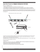
Quick Start Guide for SWM4000 WIRELESS SYSTEMS Setting up the SWM4000 Receivers. 1. Plug the PSU power supply into the wall socket and receiver and power on the unit. 2. Push the MENU button until the words “Auto Select” appear in the LCD (SW40-RH). Or, the word “SCAN” for the SW40-RF 3. Push the SET button. The SW40-RH or SW40-RF will set itself to a clear channel and display the channel on the receiver LCD. 4. Turn on a transmitter (leave the other transmitters turned off).
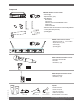
Components SW40-RH Half-Rack receivers include: • Power Supply • Dipole antennas (1 pair) • Rack Mount kit: Short rack ear Long rack ear Link bar to mount a second SW40-RH receiver 8 rack screws 4 rack mount screws • Extension cables and connectors for front-mounting antennas • 1/4 inch patch cable (not shown) • operating guide SW40-R modular receivers include: • Module Frame with 1, 2, 3 or 4 modules • Dipole antennas (1 pair) • Power Supply • Operating guide SW40-H Handheld transmitters i
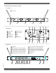
SW40-RF-Module Receiver Details Front Panel R1 Power on/off POWER SW40-RF SCALE Module B Module A R1 1.000 Module D Module C R2 R5 R6 R9 R10 R12 Module Front R2 R3 R4 R5 R6 R7 Volume (Gain) Squelch RF signal Active antenna I.R. sensor Group selection R8 R9 R10 R11 R12 R13 VOL Channel number Lock all controls Set Menu Sync Audio signal TRUE DIVERSITY RECEIVER A UHF SET ANT I.R. B GROUP CHANNEL 02 04 SW40-RM S.Q.
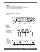
SW40-RH 1/2-Rack Receiver Details R1 R2 R4 R6 R10 R11 R12 R13 R20 Power On/Off switch - Push up to turn on, push down to turn off. Volume control. The volume control dial should generally be left in the clockwise position. Turning the dial counter-clockwise decreases receiver output level. RF LED - Indicates strength of incoming RF signal. Smart option - Press to initiate IR connection between receiver and transmitter. Set switch - Press to select the currently displayed menu option.
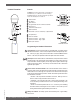
Handheld Transmitter Controls To Open: Unscrew lower portion of microphone. Pull down as you continue to turn the housing. To Close: Turn the housing and push up until it meets the threads, then screw on.
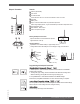
Beltpack Transmitter Controls B1 B2 B3 B1 B4 B5 B6 B2 B7 B3 B8 B9 B4 B5 Antenna (replaceable) LCD screen On-off/mute switch Press and hold to turn on or off. Press and release to mute or un-mute. Set switch Battery cover IR port - Receives infrared beam to synchronize frequencies. When using multiple systems, only one transmitter IR port should be exposed at a time.
Operating Instructions Congratulations on purchasing your Sabine SWM4000 Series Wireless Microphone System. This system is specially designed to provide you with excellent audio quality, ease of use, and reliability. Frequency Bands The SW4000 series is available in several frequency bands to accommodate various local governmental regulations throughout the world. The frequency band of your system is represented by the numbers appended to the part number.
Setting up your Wireless Systems 1. Plug the PSU power supply into the wall socket and receiver. 2. (SW40-RH) Push the MENU button until the words Auto Select appear in the LCD. (SW40-RF) Push the MENU button until the words scan appear in the LCD. 3. Push the SET button. The SW40-RH or SW-40-RF will set itself to a clear channel and display the channel on the receiver LCD. 4. Turn on a transmitter (leave the other transmitters turned off).
Appendix A Manual Programming R7 Allows manual selection of a frequency group. Pressing SET increases the group number by one. When the correct frequency is displayed press S.O. (SYNC). For best results when operating multiple systems, set all systems to a single group; then set each system to a unique channel within that group. R8 Allows manual selection of a frequency channel. Pressing SET increases the channel number by one. When the correct frequency is displayed press S.O. (SYNC).
Appendix B Frequencies and Groups FREQUENCY BAND SELECTION Most countries closely regulate radio frequency devices to limit RF (radio frequency) interference. Many countries are in the process of changing their regulations in order to accomodate requirements for DTV braodcasts and smart phones. SWM4000 systems are available in several frequency ranges. Contact your local retailer to determine the bands that are suitable in your area. Sabine is making new frequency bands available as the regulations evolve.
© 2010 Sabine, Inc.
© 2010 Sabine, Inc. Appendix E Specifications SW40 Receiver SW40-H Handheld Transmitter Operating Range Under Typical Conditions 100m (300 ft) Note: actual range depends on RF signal absorption, reflection, and interference Audio Frequency Response (+/- 2 dB) Maximum: 20 kHz Minimum: 50 Hz (Overall system frequency depends on microphone element.) Total Harmonic Distortion (ref. +/- 30 kHz deviation, 400Hz tone) 0.
© 2010 Sabine, Inc.
© 2010 Sabine, Inc. NOTES: 15 Sabine SWM4000 Smart Spectrum® Wireless LIT-SWM4000-OG-EN-100205.
03/01/2010 W I R E L E S S SYS T E M S Sabine, Inc. 13301 NW US Highway 441 Alachua, Florida 32615-8544 USA Phone: (386) 418-2000 Fax: (386) 418-2001 www.Sabine.