efesotomasyon.
efesotomasyon.
efesotomasyon.com - Control Techniques,emerson,saftronics -ac drive-servo motor PREFACE Saftronics’ FP5/GP5 is the world’s first optimized Inverter specifically designed for general-purpose applications. This manual describes installation, maintenance and inspection, troubleshooting, and specifications of the FP5/GP5. Read this manual thoroughly before operation.
efesotomasyon.com - Control Techniques,emerson,saftronics -ac drive-servo motor PREFACE Notes for Safe Operation Read this manual thoroughly before installation, operation, maintenance or inspection of the FP5/GP5. operation are classified as followed: In this manual, notes for safe WARNING Indicates a potentially hazardous situation which, if not avoided, could result in death or serious injury to personnel.
efesotomasyon.com - Control Techniques,emerson,saftronics -ac drive-servo motor PREFACE CAUTION • • • • • § Page Verify that the Inverter rated voltage coincides with the AC power supply voltage. Failure to observe this can result in personal injury or fire. Do not perform a withstand voltage test on the Inverter. It may cause semi-conductor elements to be damaged. To connect a Braking Resistor, Braking Resistor Unit or Braking Unit, follow the procedures described in Chapter 11.
efesotomasyon.com - Control Techniques,emerson,saftronics -ac drive-servo motor PREFACE § Maintenance and Inspection WARNING • • • • Page Never touch high-voltage terminals in the Inverter. Failure to observe this can result in an electrical shock. Replace all protective covers before powering up the Inverter. To remove the cover, make sure to shut OFF the Molded Case Circuit Breaker. Failure to observe this can result in an electrical shock.
efesotomasyon.com - Control Techniques,emerson,saftronics -ac drive-servo motor Table of Contents 1 Receiving .............................................................................................. 1 1.1 Inspection Checkpoints.................................................................................. 2 1.1.1 1.1.2 Receiving Checkpoints........................................................................................................ Checking the Nameplate Data ....................
efesotomasyon.com - Control Techniques,emerson,saftronics -ac drive-servo motor 6.3.6 6.3.7 6.3.8 6.3.9 6.3.10 6.3.11 6.3.12 6.3.13 6.3.14 6.3.15 6.3.16 6.4 8 9 12 Intended Value Setting........................................................................................................ Detected Value Setting ....................................................................................................... 58 58 Energy Saving Gain K2 (n096)....................................................
efesotomasyon.com - Control Techniques,emerson,saftronics -ac drive-servo motor 1 Receiving This chapter describes how to inspect the inverter after delivery to the user. 1.1 Inspection Checkpoints.................................................. 1.1.1 1.1.2 1.2 Receiving Checkpoints ....................................................................................... Checking the Nameplate Data ........................................................................... Identifying the Parts.......
efesotomasyon.com - Control Techniques,emerson,saftronics -ac drive-servo motor Chapter 1: Receiving CAUTION • 1.1 Do not install or operate any Inverter which is damaged or has missing parts. Failure to observe this may result in personal injury or equipment damage. Inspections Checkpoints 1.1.
efesotomasyon.com - Control Techniques,emerson,saftronics -ac drive-servo motor Chapter 1: Receiving § Specification Designation ∗ For special specifications, a spec sheet number appears on the nameplate. Figure 3 Specification Designation 1.2 Identifying the Parts Figure 4 Configuration of FP5/GP5 Firmware – S2011 and S3012 Revision: 1 (9/98) 3 © Saftronics, Inc.
efesotomasyon.com - Control Techniques,emerson,saftronics -ac drive-servo motor Chapter 1: Receiving NOTES: Firmware – S2011 and S3012 Revision: 1 (9/98) 4 © Saftronics, Inc.
efesotomasyon.com - Control Techniques,emerson,saftronics -ac drive-servo motor 2 Installation This chapter describes configuration, location and clearances when mounting the FP5/GP5. 2.1 Removing and Replacing the Digital Operator............. 2.1.1 2.1.2 Removing the Digital Operator........................................................................... Replacing the Digital Operator ........................................................................... 6 6 6 2.
efesotomasyon.com - Control Techniques,emerson,saftronics -ac drive-servo motor Chapter 2: Installation CAUTION • • • When moving the unit, lift the cabinet by the base, never lift by the front cover. Otherwise, the main unit may be dropped causing damage to the unit. Mount the Inverter on nonflammable material, (i.e., metal). Failure to observe this can result in a fire. When mounting units in an enclosure, install a fan or other cooling device to keep the intake air temperature below 45°C.
efesotomasyon.com - Control Techniques,emerson,saftronics -ac drive-servo motor Chapter 2: Installation 2.2 Removing and Replacing the Front Cover To remove the front cover, first move the Digital Operator in the direction shown by arrow 1. (Figure 5). Then squeeze the cover in the direction shown by arrows 2 on both sides and lift in the direction shown by arrow 3. Figure 7 Removing and Replacing the Front Cover NOTE: 2.3 Do not replace the front cover with the Digital Operator connected.
efesotomasyon.com - Control Techniques,emerson,saftronics -ac drive-servo motor Chapter 2: Installation 2.4 Clearances Install the FP5/GP5 vertically and allow sufficient clearances for effective cooling as shown below. Figure 8 Clearances NOTE: 1. The clearances required at the top and bottom and both sides are common in open chassis type (IP00) and enclosed wall-mounted type (NEMA1/IP20). 2. Remove the top and bottom covers to use the open chassis type of 200V/400V 15kW or less. 3.
efesotomasyon.com - Control Techniques,emerson,saftronics -ac drive-servo motor 3 Wiring This chapter describes the main circuit wiring and the control circuit wiring of the FP5/GP5. 3.1 3.2 Connection Diagram ....................................................... 10 Wiring the Main Circuit ................................................... 11 3.2.1 3.2.2 3.2.3 3.2.4 3.2.5 3.2.6 3.3 11 12 12 13 15 17 Wiring the Control Circuit .............................................. 21 3.3.1 3.3.2 3.3.3 3.
efesotomasyon.com - Control Techniques,emerson,saftronics -ac drive-servo motor Chapter 3: Wiring WARNING • • • Only commence wiring after verifying that the power supply is turned OFF. Failure to observe this can result in an electrical shock or fire. Wiring should be performed only by qualified personnel. Failure to observe this can result in an electrical shock or fire. When wiring the emergency stop circuit, check the wiring thoroughly before operation.
efesotomasyon.com - Control Techniques,emerson,saftronics -ac drive-servo motor Chapter 3: Wiring NOTE: 3.2 P 1. indicates shielded wires and indicates twisted-pair shielded wires. 2. Voltage or current input for the master frequency reference can be selected by constant n042. Voltage reference input is preset at the factory (FV). 3. Control circuit Terminal FS of + 15V has a maximum output current capacity of 20 mA. 4. Multi-function analog output should be used for monitoring meters (e.g.
efesotomasyon.com - Control Techniques,emerson,saftronics -ac drive-servo motor Chapter 3: Wiring § Installation of Surge Suppressor For inductive loads (magnetic contactors, magnetic relays, magnetic valves, solenoids, magnetic brakes, etc.) connected near the Inverter, use a surge suppressor simultaneously.
efesotomasyon.com - Control Techniques,emerson,saftronics -ac drive-servo motor Chapter 3: Wiring • • Use the ground wires described in Tables 5 or 6 and keep the length as short as possible. When using several Inverter units side by side, ground the units as shown in Figure 10, (a) or (b). Do not loop the ground wires as shown in (c). Figure 10 Grounding of Three Inverter Units 3.2.4 Functions of Main Circuit Terminals The following table outlines the functions of the main circuit terminals.
efesotomasyon.com - Control Techniques,emerson,saftronics -ac drive-servo motor Chapter 3: Wiring Table 4 Models FP5/GP5 40P4 to 4015 4018 to 4045 4055 to 4160 4185 to 4300 Max Applicable Motor Output 0.4 to 15 kW 18.
efesotomasyon.com - Control Techniques,emerson,saftronics -ac drive-servo motor Chapter 3: Wiring 3.2.5 Main Circuit Configuration 200V Class FP5/GP523P7 to FP5/GP527P5 FP5/GP52011 to FP5/GP52015 FP5/GP52018 to FP5/GP52022 FP5/GP52030 to FP5/GP52075 = The wiring has been completed at the factory prior to shipping. ‡ When installing a DC Reactor (option) on models of 15kW or below, remove the short-circuit bar between ¾ 1 and ¾2 terminals and connect a DC Reactor with the terminals.
efesotomasyon.com - Control Techniques,emerson,saftronics -ac drive-servo motor Chapter 3: Wiring 400V Class FP5/GP540P4 to FP5/GP541P5 FP5/GP542P2 to FP5/GP54015 FP5/GP54018 to FP5/GP54045 FP5/GP54055 to FP5/GP54160 FP5/GP54185 to FP5/GP54300 = The wiring has been completed at the factory prior to shipping. ‡ When installing a DC Reactor (option) on models of 15kW or below, remove the short-circuit bar between ¾ 1 and ¾ 2 terminals and connect a DC Reactor with the terminals.
efesotomasyon.com - Control Techniques,emerson,saftronics -ac drive-servo motor Chapter 3: Wiring 3.2.6 Parts Required for Wiring Select wires or Closed-Loop Connectors to be used for wiring from Tables 5, 6 and 7. Table 5 Model FP5/GP5 Circuit mm 10 5.5 8 8 10-8 5.5 − 8 8 8 10-8 5.
efesotomasyon.com - Control Techniques,emerson,saftronics -ac drive-servo motor Chapter 3: Wiring Table 6 Model FP5/GP5 Circuit Terminal Screw Terminal Symbol Wire Size = AWG mm 2 40P4 L1, L2, L3, (R, S, T), Ö, ¾ 1, ¾ 2, B1, B2, T1, T2, T3 (U, V, W) M4 2 − 5.5 40P7 L1, L2, L3 (R, S, T), Ö, ¾ 1, ¾ 2, B1, B2, T1, T2, T3 (U, V, W) M4 2 − 5.5 41P5 L1, L2, L3, (R, S, T), Ö, ¾ 1, ¾ 2, B1, B2, T1, T2, T3 (U, V, W) M4 2 − 5.
efesotomasyon.
efesotomasyon.com - Control Techniques,emerson,saftronics -ac drive-servo motor Chapter 3: Wiring Table 7 NOTE: Closed-Loop Connectors AWG Size Wire Size mm 20 0.5 18 0.75 16 1.25 14 2 12-10 3.5 / 5.5 8 8 6 14 4 22 3-2 30 / 38 1-1/0 50 / 60 3/0 4/0 4/0 300MCM 400MCM 80 100 100 150 200 650MCM 325 2 Terminal Screw M3.5 M4 M3.5 M4 M3.5 M4 M3.5 M4 M5 M6 M8 M4 M5 M6 M8 M5 M6 M8 M6 M8 M6 M8 M8 M8 M10 M10 M12 M12 x 2 M16 Closed-Loop Connectors 1.25 − 3.5 1.25 − 4 1.25 − 3.5 1.
efesotomasyon.com - Control Techniques,emerson,saftronics -ac drive-servo motor Chapter 3: Wiring 3.3 Wiring the Control Circuit The following table outlines the functions of the control circuit terminals. Wire according to each terminal function. 3.3.
efesotomasyon.com - Control Techniques,emerson,saftronics -ac drive-servo motor Chapter 3: Wiring 3.3.2 Wiring the Control Circuit Terminals Insert the wire into the lower part of the terminal block and connect it tightly with a screwdriver. Wire sheath strip length must be 7 mm (approximately ¼ inch). 3.3.3 Precautions on Control Circuit Wiring • • Separate control circuit wires from main circuit wires and other power cables to prevent erroneous operation caused by noise interference.
efesotomasyon.com - Control Techniques,emerson,saftronics -ac drive-servo motor 4 Operation This chapter describes the basic operation procedures of the FP5/GP5. 4.1 Operation Mode Selection......................................... 25 4.2 Test Run Checkpoints ............................................... 26 4.3 Setting the Line Voltage Using Jumper (For 400V Class 18.5kW and Above) ........................ 26 4.4 Test Run...................................................................... 27 4.
efesotomasyon.com - Control Techniques,emerson,saftronics -ac drive-servo motor Chapter 4: Operation WARNING • • • Only turn ON the input power supply after replacing the front cover. Do not remove the cover while current is flowing. Failure to observe this can result in an electrical shock. When the retry function (n057) is selected, do not approach the Inverter or the load, since it may restart suddenly after being stopped.
efesotomasyon.com - Control Techniques,emerson,saftronics -ac drive-servo motor Chapter 4: Operation 4.1 Operation Mode Selection The FP5/GP5 has two operation modes, LOCAL and REMOTE, as described in Table 9. These two modes can be selected by the Digital Operator LOCAL/REMOTE key only while the operation is stopped. The selected Operation mode can be verified by observing the Digital Operator SEQ and REF LED’s as shown below.
efesotomasyon.com - Control Techniques,emerson,saftronics -ac drive-servo motor Chapter 4: Operation 4.2 Test Run Checkpoints To assure safety, prior to initial operation, disconnect the machine coupling so that the motor is isolated from the machine. If initial operation must be performed while the motor is still coupled to the machine, use great care to avoid potentially hazardous conditions. Check the following items before a test run. 4.3 o Wiring and terminal connections are correct.
efesotomasyon.com - Control Techniques,emerson,saftronics -ac drive-servo motor Chapter 4: Operation 4.4 Test Run 4.4.1 Digital Operator Display at Power-up When the system is ready for operation, turn ON the power supply. Verify that the Inverter powers up properly. If any problems are found, turn OFF the power supply immediately. The Digital Operator display illuminates as shown below when turning the power supply ON.
efesotomasyon.com - Control Techniques,emerson,saftronics -ac drive-servo motor Chapter 4: Operation 4.4.2 Operation Check Points Check the following items during operation. 4.4.3 o Motor rotates smoothly. o Motor rotates in the correct direction. o Motor does not have abnormal vibration or noise. o Acceleration and deceleration are smooth. o Current matches the load flow. o Status indicator LED’s and Digital Operator display are correct. Example of Basic Operation.
efesotomasyon.com - Control Techniques,emerson,saftronics -ac drive-servo motor Chapter 4: Operation Table 10 Typical Operation by Digital Operator (continued) ¯ Frequency Reference Value Change (15 Hz to 60 Hz) • Select frequency reference value display. • Change set value. Press 7 times Change the value by pressing 15.0 Fref \ / 60.0 Fref 60.0 Fref 60.0 Fref / \ • Write-in set value. • Select output frequency monitor display. ° Reverse Run • Select reverse run.
efesotomasyon.com - Control Techniques,emerson,saftronics -ac drive-servo motor Chapter 4: Operation Table 11 Typical Operation by Control Circuit Terminal Signal ¬ - Description Power ON • Display frequency reference value. REMOTE mode is preset at the factory Key Sequence Frequency Setting • Input frequency reference voltage (current) by control circuit Terminal FV or FI and verify the input value by the Digital Operator. 0.0 Fref 60.0 Fref 0.0 Fout 60.0 Fout 0.
efesotomasyon.com - Control Techniques,emerson,saftronics -ac drive-servo motor 5 Simple Data Setting This chapter describes simple data setting. 5.1 Digital Operator Key Description................................... 32 5.2 LED Description ..............................................................
efesotomasyon.com - Control Techniques,emerson,saftronics -ac drive-servo motor Chapter 5: Simple Data Setting 5.1 Digital Operator Key Description Mode Indicator LED’s (Remote Mode) Lights when selecting Input mode from the control circuit terminal or serial communication. SEQ: Lights when selecting RUN command from control circuit terminal or serial communication. REF: Lights when selecting frequency reference from control circuit Terminals FV and FI or serial communication.
efesotomasyon.com - Control Techniques,emerson,saftronics -ac drive-servo motor Chapter 5: Simple Data Setting Table 12 LED Description LED Display Description Key Sequence Digital Operator Display Remarks Power ON Fref Frequency reference setting/monitoring 0.0 Fout Output frequency monitor 0.0 Iout Output current monitor 0.0 kWout Output power monitor 0.0 Press ENTER key to display the monitor value.
efesotomasyon.com - Control Techniques,emerson,saftronics -ac drive-servo motor Chapter 5: Simple Data Setting NOTES: Firmware – S2011 and S3012 Revision: 1 (9/98) 34 © Saftronics, Inc.
efesotomasyon.com - Control Techniques,emerson,saftronics -ac drive-servo motor 6 Programming Features This chapter describes programming features. 6.1 Constant Set-Up and Initialization ................................. 36 6.1.1 6.2 Using Sequence Input Signals (n035 to n039).................................................. Using Analog Input Signals (n042 to n045) ....................................................... Using Output Signals (n040, n041)................................................
efesotomasyon.com - Control Techniques,emerson,saftronics -ac drive-servo motor Chapter 6: Programming Features 6.1 Constant Set-up and Initialization 6.1.1. Constant Selection/Initialization (n001) The following table describes the data which can be set or read when n001 is selected.
efesotomasyon.com - Control Techniques,emerson,saftronics -ac drive-servo motor Chapter 6: Programming Features 6.2.1. Preset V/f Pattern The following shows the preset V/f patterns. (The voltages are for 200V class. For 400V class, the value is twice that of 200V class.
efesotomasyon.com - Control Techniques,emerson,saftronics -ac drive-servo motor Chapter 6: Programming Features 6.2.2. Custom V/f Pattern Set each pattern when using a special motor (high-speed motor, etc.) or when requiring special torque adjustment of machine. Make sure to satisfy the following conditions for setting of constants n012 to n018. n017 < n015 < n014 < n012 Figure 18 Constant No. n012 Name Maximum output frequency Custom V/f Pattern Setting Unit Setting Range Factory Setting 0.
efesotomasyon.com - Control Techniques,emerson,saftronics -ac drive-servo motor Chapter 6: Programming Features Figure 19 Multi-Speed Selection – Control Circuit Terminals Figure 20 Multi-Step Speed Operation Timing Diagram 6.3.3. Operating at Low Speed Set jog frequency reference selection in multi-function contact input terminals (S2 to S6). Then input a FWD or REV RUN command. Operation is enabled at the jog frequency set in n029.
efesotomasyon.com - Control Techniques,emerson,saftronics -ac drive-servo motor Chapter 6: Programming Features 6.3.4. Adjusting Frequency Setting Signal When the frequency reference is output by an analog input of control circuit Terminals FV and FI, the relationship between the analog input (voltage/current) and the frequency reference can be set.
efesotomasyon.com - Control Techniques,emerson,saftronics -ac drive-servo motor Chapter 6: Programming Features 6.3.5. Adjusting Frequency Upper and Lower Limits Figure 24 Setting Frequency Upper and Lower Limits § § Frequency Reference Upper Limit (n030) Sets the upper limit of the frequency reference in units of 1%. (n012 Maximum output frequency: 100%) Factory setting: 100% Frequency Reference Lower Limit (n031) Sets the lower limit of the frequency reference in units of 1%.
efesotomasyon.com - Control Techniques,emerson,saftronics -ac drive-servo motor Chapter 6: Programming Features 6.3.7 Automatic Restart after Momentary Power Loss (n051) When momentary power loss occurs, operation restarts automatically. Setting Description 0 Not provided (Factory setting) 1[ Continuous operation after power recovery within 2 seconds Continuous operation after power recovery within control logic time 2= 6.3.8. (No fault output. Restarts only while control power supply is ON.
efesotomasyon.com - Control Techniques,emerson,saftronics -ac drive-servo motor Chapter 6: Programming Features 6.3.9 Torque Detection If an excessive load is applied to the machine, output current increase can be detected by output alarm signals at multifunction contact output Terminals MA, MB and M1. To output an overtorque detection signal, set multi-function contact output selection n040 or n041 to “overtorque detection” [Setting: 6 (NO contact) or 7 (NC contact)].
efesotomasyon.com - Control Techniques,emerson,saftronics -ac drive-servo motor Chapter 6: Programming Features 6.3.10 Frequency Detection (n073) Effective when multi-function contact output selections n040 or n041 are set to frequency detection (Setting: 4 or 5). Frequency detection turns ON when output frequency is higher or lower than the frequency detection level (n073). § Frequency Detection (Output Frequency < Frequency Detection Level) (Set n040 or n041 to 4.
efesotomasyon.com - Control Techniques,emerson,saftronics -ac drive-servo motor Chapter 6: Programming Features 6.3.12 Continuing Operation by Automatic Fault Reset (n056) Sets the Inverter to restart and reset fault detection after a fault occurs. The number of self-diagnosis and retry attempts can be set in n056 up to 10.
efesotomasyon.com - Control Techniques,emerson,saftronics -ac drive-servo motor Chapter 6: Programming Features § DC Injection Braking at Start (n064, n066) Restarts a coasting motor after stopping it. Set the DC Injection Braking time at start in constant n066 in units of 0.1 second. When constant n066 is set to 0, DC Injection Braking is not performed and acceleration starts from the minimum output frequency. Set DC Injection Braking current in constant n064 in units of 1%.
efesotomasyon.com - Control Techniques,emerson,saftronics -ac drive-servo motor Chapter 6: Programming Features 6.3.16 Reducing Motor Noise or Leakage Current (n050) Sets Inverter output transistor switching frequency (carrier frequency). Setting Carrier Frequency (kHz) Metallic Noise from Motor Noise and Current Leakage 1 2.5 Higher Smaller 2 5.0 Not audible Larger 3 8.0 4 10.0 5 12.5 6 15.
efesotomasyon.com - Control Techniques,emerson,saftronics -ac drive-servo motor Chapter 6: Programming Features 6.4 Selecting Stopping Method 6.4.1. Selecting Stopping Method (n004) Selects the stopping method suitable for the application.
efesotomasyon.com - Control Techniques,emerson,saftronics -ac drive-servo motor Chapter 6: Programming Features 6.4.2. Coast to Stop with Timer § Coast to Stop with Timer 1 (n004 = 2) Example of accel/decel time 1 selection Figure 38 Example of Stopping Method (Coast to Stop with Timer) A RUN command is not accepted while the motor decelerates after a STOP command is given.
efesotomasyon.com - Control Techniques,emerson,saftronics -ac drive-servo motor Chapter 6: Programming Features Figure 40 DC Injection Braking When coast to stop is specified in stopping method selection (n004), DC Injection Braking at stop does not operate. 6.5 Building Interface Circuits with External Devices 6.5.1. Using Sequence Input Signals (n035 to n039) Multi-function contact input Terminal S2 to S6 functions can be changed when necessary by setting constants n035 to n039, respectively.
efesotomasyon.com - Control Techniques,emerson,saftronics -ac drive-servo motor Chapter 6: Programming Features § Terminal Function at 2-Wire Sequence Selection (Setting: 0) Figure 41 Terminal Function at 2-Wire Sequence Selection § Terminal Function at 3-Wire Sequence Selection (Setting: 1) Figure 42 Terminal Function at 2-Wire Sequence Selection § LOCAL/REMOTE Selection (Setting: 5) Selects operation reference by the Digital Operator or by the control circuit terminal.
efesotomasyon.com - Control Techniques,emerson,saftronics -ac drive-servo motor Chapter 6: Programming Features § Timer Function (Setting: 20) When the timer function input is longer than ON-delay timer (n077), the timer function output closes. When the timer input is open for longer than OFF-delay timer (n078), the timer function output opens.
efesotomasyon.com - Control Techniques,emerson,saftronics -ac drive-servo motor Chapter 6: Programming Features The following shows the time chart at UP/DOWN command input. Figure 45 Timing Diagram of VP/Down Command Input NOTE: U = UP (accelerating) status D = DOWN (decelerating) status H = HOLD (constant Speed) status U1 = UP status, clamping at upper limit speed D1 = DOWN status, clamping at lower limit speed 1.
efesotomasyon.com - Control Techniques,emerson,saftronics -ac drive-servo motor Chapter 6: Programming Features § Auxiliary Analog Input Selection (n043) To change the control circuit Terminal FI input level, set constant n043. NOTE: Setting FI Terminal Input Level 0 0 to 10 V input 1 4 to 20 mA input To set constant n043 to 0, cut jumper J1 on the Inverter control PC board.
efesotomasyon.com - Control Techniques,emerson,saftronics -ac drive-servo motor Chapter 6: Programming Features 6.5.3. Using Output Signals (n040, n041) Multi-function contact output Terminals MA, MB and M1 functions can be changed when necessary by setting constants n040 and n041. • Terminal MA and MB functions: Set to n040. • Terminal M1 function: Set to n041. Table 16 Multi-Function Output Variables Setting Name Description Page Fault Closed when Inverter fault occurs.
efesotomasyon.com - Control Techniques,emerson,saftronics -ac drive-servo motor Chapter 6: Programming Features § Setting Example of Frequency Agree Signal (Setting: 2) Figure 46 Example of Frequency Agree Signal § Setting Example of Desired Frequency Agree Signal (Setting: 3) Figure 47 Example of Desired Frequency Agree Signal 6.6 Adjusting Motor Torque 6.6.1. Torque Compensation Gain (n067) Motor torque requirement changes according to load conditions.
efesotomasyon.com - Control Techniques,emerson,saftronics -ac drive-servo motor Chapter 6: Programming Features 6.7 Motor Protection 6.7.1. Motor Overload Detection The Inverter protects against motor overload with a built-in electronic Thermal Overload Relay. § Motor Rated Current (n032) Set to the rated current value shown on the motor nameplate.
efesotomasyon.com - Control Techniques,emerson,saftronics -ac drive-servo motor Chapter 6: Programming Features 6.8 PID Control To enable PID Control, set PID selection (n084) from 1 to 3. Setting Description 0 PID disabled 1 PID enabled (Deviation I D-controlled.) 2 PID with feed forward (Feedback value is D-controlled.) 3 PID with feed forward (Feedback is reversed characteristics.) Then select the PID Control intended value or detected value settings as follows. 6.8.1.
efesotomasyon.com - Control Techniques,emerson,saftronics -ac drive-servo motor Chapter 6: Programming Features 6.9 Energy Saving Control To enable Energy Saving Control, set energy saving selection (n095) to 1. Setting Description 0 Energy saving is disabled 1 Energy saving is enabled Since the constants used in the Energy Saving Control mode have been preset at the factory to the optimum values prior to shipment, it is not necessary to adjust them under normal operation.
efesotomasyon.com - Control Techniques,emerson,saftronics -ac drive-servo motor Chapter 6: Programming Features § Step Voltage of Tuning (n100, n101) Sets voltage variation width of one tuning cycle. Setting is made in a percentage of motor rated voltage. By increasing this value, the rotating speed variation becomes larger. This voltage variation width is set when starting tuning voltage is 100% and motor rated voltage is 5%.
efesotomasyon.com - Control Techniques,emerson,saftronics -ac drive-servo motor Chapter 6: Programming Features § MEMOBUS Frequency Reference Unit (n105) The frequency reference units from the PLC and in the frequency reference and output frequency monitors (by communication) are selected. The output frequency resolution of the FP5/GP5 is 0.1 Hz. Even if the frequency reference unit is changed to 0.01 Hz in constant n105, the value in the hundredth digit of 0.
efesotomasyon.com - Control Techniques,emerson,saftronics -ac drive-servo motor Chapter 6: Programming Features NOTES: Firmware – S2011 and S3012 Revision: 1 (9/98) 62 © Saftronics, Inc.
efesotomasyon.com - Control Techniques,emerson,saftronics -ac drive-servo motor 7 Maintenance and Inspection This chapter describes basic maintenance and inspection procedures for the FP5/GP5. 7.1 Periodic Inspector........................................................... 64 7.2 Parts Replacement Schedule (Guidelines) ...................
efesotomasyon.com - Control Techniques,emerson,saftronics -ac drive-servo motor Chapter 7: Maintenance and Inspection WARNING • • • • Never touch high-voltage terminals in the Inverter. Failure to observe this can result in an electrical shock. Replace all protective covers before powering up the Inverter. To remove the cover, make sure to shut OFF the Molded Case Circuit Breaker. Failure to observe this can result in an electrical shock.
efesotomasyon.com - Control Techniques,emerson,saftronics -ac drive-servo motor 8 Troubleshooting This chapter describes the Inverter fault display and the fault contents caused by motor/machine malfunctions and the corrective actions to be taken. 8.1 Fault Diagnosis and Corrective Actions ....................... 66 8.2 Alarm Display and Explanation ..................................... 69 8.3 Motor Faults and Corrective Actions ............................
efesotomasyon.com - Control Techniques,emerson,saftronics -ac drive-servo motor Chapter 8: Troubleshooting 8.1 Fault Diagnosis and Corrective Actions § § § § NOTE: When the FP5/GP5 detects a fault, the fault is displayed on the Digital Operator and activates the fault contact output and the motor coasts to a stop. Check the cause in the table below and take the corrective actions.
efesotomasyon.com - Control Techniques,emerson,saftronics -ac drive-servo motor Chapter 8: Troubleshooting Table 20 Fault Display Description Fault Diagnosis and Corrective Actions Details Corrective Action 1 Main circuit undervoltage (PUV) Undervoltage in the DC main circuit during running. Detection level: 200 V class: Approximately 190 V or less. 400 V class: Approximately 380 V or less. U 2 Control circuit undervoltage (CUV) Undervoltage in the control circuit during running.
efesotomasyon.com - Control Techniques,emerson,saftronics -ac drive-servo motor Chapter 8: Troubleshooting Table 20 Fault Display Description Fault Diagnosis and Corrective Actions (Continued) Details Corrective Action EF2 External fault at Terminal S2 EF3 External fault at Terminal S3 EF4 External fault at Terminal S4 EF5 External fault at Terminal S5 EF6 External fault at Terminal S6 SPI Excessive ripple in bus bar • Inverter input power supply has open-phase.
efesotomasyon.com - Control Techniques,emerson,saftronics -ac drive-servo motor Chapter 8: Troubleshooting 8.2 Alarm Display and Explanation Alarms do not activate fault contact outputs and the Inverter returns to its former operation status automatically when the cause is removed. The following table explains the different types of alarms. Table 21 Alarm Display U Alarm Display and Explanation Contents Explanation Undervoltage detection Undervoltage has been detected.
efesotomasyon.com - Control Techniques,emerson,saftronics -ac drive-servo motor Chapter 8: Troubleshooting 8.3 Motor Faults and Corrective Actions § § If any of the following faults occurs in the motor, check the cause and provide the relevant corrective action. If these inspections and corrective actions cannot solve the problem, contact your Saftronics representative immediately.
efesotomasyon.com - Control Techniques,emerson,saftronics -ac drive-servo motor 9 Specifications This chapter describes the specifications of the FP5/GP5 Inverter. 9.1 Standard Specifications .................................................
efesotomasyon.com - Control Techniques,emerson,saftronics -ac drive-servo motor Chapter 9: Specifications 9.1 Standard Specifications Table 23 200 V Class Specifications Series Models FP5/GP5 Power Supply Output Characteristics Maximum Applicable Motor Output *(kW) Inverter Capacity (kVA) Rated Output Current (A) FP5/GP5 23P7 25P5 27P5 2011 2015 2018 2022 2030 2037 2045 2055 2075 3.7 5.5 7.5 11 15 18.5 22 30 37 45 55 75 6.7 9.5 13 19 24 30 37 50 61 70 85 110 17.
efesotomasyon.com - Control Techniques,emerson,saftronics -ac drive-servo motor Chapter 9: Specifications Table 24 Models FP5/GP5 40P4 40P7 41P5 42P2 43P7 44P0 45P5 47P5 4011 4015 0.55 1.1 1.5 2.2 3.7 4.0 5.5 7.5 11 15 Inverter Capacity (kVA) 1.4 2.6 3.7 4.7 6.1 8.4 11 14 21 26 Rated Output Current (A) 1.8 3.4 4.8 6.
efesotomasyon.com - Control Techniques,emerson,saftronics -ac drive-servo motor Chapter 9: Specifications Table 25 Models FP5/GP5 4018 4022 4030 4037 4045 4055 4075 4110 4160 4185 4220 4300 18.
efesotomasyon.com - Control Techniques,emerson,saftronics -ac drive-servo motor 10 Dimensions The following chapter describes the dimensions of the FP5/GP5. 10.1 Dimensions......................................................................
efesotomasyon.com - Control Techniques,emerson,saftronics -ac drive-servo motor Chapter 10: Dimensions 10.1 Dimensions The figures below show a 200V 3.7kW model. Use open chassis type 200V/400V 15kW or less with the top and bottom covers removed. Figure 52 Dimensions of FP5/GP5 The following figure shows the mounting dimensions of 400V 185 to 300kW.
efesotomasyon.com - Control Techniques,emerson,saftronics -ac drive-servo motor Chapter 10: Dimensions Table 26 Voltage Open Chassis Type (IP00) Motor Capacity (kW) W H D W1 H1 3.7 140 280 180 126 266 5.5 7.5 11 15 200V Class FP5/GP5 Dimensions (mm) and Approximate Mass (kg) 18.5 22 30 37 45 55 75 0.55 1.1 Enclosed Wall-mounted type (NEMA1/IP20) H2 Mass (kg) W H H W1 H1 H2 Mass (kg) d* 7.0 4.5 140 280 180 126 266 7.0 4.5 M5 5.5 200 300 205 186 285 8.
efesotomasyon.com - Control Techniques,emerson,saftronics -ac drive-servo motor Chapter 10: Dimensions NOTES: Firmware – S2011 and S3012 Revision: 1 (9/98) 78 © Saftronics, Inc.
efesotomasyon.com - Control Techniques,emerson,saftronics -ac drive-servo motor 11 Typical Connection Diagram This chapter describes the connection diagrams for the GP5. 11.1 Braking Resistor Unit ..................................................... 80 11.2 Braking Unit and Braking Resistor Unit........................
efesotomasyon.com - Control Techniques,emerson,saftronics -ac drive-servo motor Chapter 11: Typical Connection Diagram 11.1 Braking Resistor Unit For Models GP5 23P7 to − GP5 27P5 (200 V Class 3.7 to 7.5 kW). Models GP5 40P4 TP − GP5 4015 (400 V Class 0.4 to 15 kW). GP5 = The transformer is not necessary for 200V class. ‡ When installing a DC Reactor (option), remove the common bar between ¾1 and ¾2 terminals (provided as standard) and connect a DC Reactor with the terminals.
efesotomasyon.com - Control Techniques,emerson,saftronics -ac drive-servo motor Chapter 11: Typical Connection Diagram 11.2 Braking Unit and Braking Resistor Unit For models GP5 2011, − GP5 2015 (200 V Class 11, 15 kW). GP5 = ‡ When installing a DC Reactor (option), remove the common bar between ¾1 and ¾2 terminals (provided as standard) and connect a DC Reactor with the terminals. When using the Thermal Overload Relay, set constant n070 to 0. (Stall Prevention selection during decel is disabled.
efesotomasyon.com - Control Techniques,emerson,saftronics -ac drive-servo motor Chapter 11: Typical Connection Diagram NOTES: Firmware – S2011 and S3012 Revision: 1 (9/98) 82 © Saftronics, Inc.
efesotomasyon.com - Control Techniques,emerson,saftronics -ac drive-servo motor 12 Constant List This chapter lists the constants for the FP5/GP5. 12.1 Constant List ...................................................................
efesotomasyon.com - Control Techniques,emerson,saftronics -ac drive-servo motor Chapter 12: Constant List 12.
efesotomasyon.
efesotomasyon.
efesotomasyon.
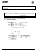
efesotomasyon.com - Control Techniques,emerson,saftronics -ac drive-servo motor Chapter 12: Constant List Table 27 Constant n082 n083 Function Name Description Output phase loss detection level (SPO) Output phase loss detection delay time (SPO) Unit : 1% Setting range : 0 to 100% Unit : 0.1 seconds Setting range : 0.0 to 2.
efesotomasyon.
efesotomasyon.com - Control Techniques,emerson,saftronics -ac drive-servo motor Chapter 12: Constant List NOTES: Firmware – S2011 and S3012 Revision: 1 (9/98) 90 © Saftronics, Inc.
efesotomasyon.com - Control Techniques,emerson,saftronics -ac drive-servo motor 13 Digital Operator Monitor Display This chapter describes the monitor displays of the Digital Operator of the FP5/GP5. 13.1 Digital Operator Monitor Display ...................................
efesotomasyon.com - Control Techniques,emerson,saftronics -ac drive-servo motor Chapter 13: Digital Operator Monitor Display 13.1 Digital Operator Monitor Display The following table shows the contents of the Digital Operator monitor display. Table 28 Digital Operator Monitor Display LED Name Fref Frequency reference Fout Output frequency Iout Output current kWout Output voltage Output voltage can be monitored in units of 0.1 kW (1 kW for 1000 k and above).
efesotomasyon.com - Control Techniques,emerson,saftronics -ac drive-servo motor Chapter 13: Digital Operator Monitor Display Table 28 LED Digital Operator Monitor Display (Continued) Name Description No. Contents U−09 Maximum 4 faults can be monitored. U−10 Lower 4 digits of PROM number can be monitored. Elapsed time can be monitored as follows.
efesotomasyon.com - Control Techniques,emerson,saftronics -ac drive-servo motor Chapter 13: Digital Operator Monitor Display NOTES: Firmware – S2011 and S3012 Revision: 1 (9/98) 94 © Saftronics, Inc.
efesotomasyon.
efesotomasyon.
efesotomasyon.
efesotomasyon.com - Control Techniques,emerson,saftronics -ac drive-servo motor INDEX V W V/f data setting error, 68 V/f pattern selection, 84, 93 V/f reduction level during speed search, 86 vibration, 70 voltage limit of tuning, 59, 88 wire size, 17, 18, 19 withstand voltage test, iii, 10 Firmware – S2011 and S3012 Revision: 1 (9/98) 98 © Saftronics, Inc.
efesotomasyon.
efesotomasyon.com - Control Techniques,emerson,saftronics -ac drive-servo motor 5580 Enterprise Parkway, Fort Myers, Florida 33905 l Telephone (941) 693-7200 l Fax (941) 693-2431 Web Address: http://www.saftronics.