
Specifications


Firmware – S2011 and S3012
Revision: 1 (9/98) v © Saftronics, Inc.
Table of Contents
1 Receiving .............................................................................................. 1
1.1 Inspection Checkpoints.................................................................................. 2
1.1.1 Receiving Checkpoints........................................................................................................ 2
1.1.2 Checking the Nameplate Data............................................................................................ 2
1.2 Identifying the Parts ....................................................................................... 2
2 Installation ............................................................................................ 5
2.1 Removing and Replacing the Digital Operator................................................ 6
2.1.1 Removing the Digital Operator .......................................................................................... 6
2.1.2 Replacing the Digital Operator............................................................................................ 6
2.2 Removing and Replacing the Front Cover...................................................... 7
2.3 Choosing a Location to Mount the Inverter..................................................... 7
2.4 Clearances .................................................................................................... 8
3 Wiring .................................................................................................... 9
3.1 Connection Diagram...................................................................................... 10
3.2 Wiring the Main Circuit................................................................................... 11
3.2.1 Wiring Precautions for Main Circuit Point........................................................................... 11
3.2.2 Wiring Precautions for Main Circuit Output ........................................................................ 12
3.2.3 Grounding............................................................................................................................ 12
3.2.4 Functions of Main Circuit Terminals ................................................................................... 13
3.2.5 Main Circuit Configuration................................................................................................... 15
3.2.6 Parts Required for Wiring.................................................................................................... 17
3.3 Wiring the Control Circuit ............................................................................... 21
3.3.1 Functions of Control Circuit Terminals ............................................................................... 21
3.3.2 Wiring the Control Circuit Terminals................................................................................... 22
3.3.3 Precautions on Control Circuit Wiring................................................................................. 22
3.4 Wiring Inspection ........................................................................................... 22
4 Operation .......................................................................................... 23
4.1 Operation Mode Selection.............................................................................. 25
4.2 Test Run Checkpoints.................................................................................... 26
4.3 Setting the Line Voltage Using Jumper (For 400V Class 18.5kW and Above). 26
4.4 Test Run........................................................................................................ 27
4.4.1 Digital Operator Display at Power-Up................................................................................. 27
4.4.2 Operation Check Points ...................................................................................................... 28
4.4.3 Example of Basic Operation ............................................................................................... 28
5 Simple Data Setting.............................................................................. 31
5.1 Digital Operator Key Description .................................................................... 32
5.2 LED Description............................................................................................. 32
6 Programming Features ........................................................................ 35
6.1 Constant Set-Up and Initialization .................................................................. 36
6.1.1 Constant Selection/Initialization (n001).............................................................................. 36
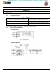
6.2 V/f Pattern Setting.......................................................................................... 36
6.2.1 Preset V/f Pattern................................................................................................................ 37
6.2.2 Custom V/f Pattern.............................................................................................................. 38
6.3 Setting Operation Conditions ......................................................................... 38
6.3.1 Reverse Run Prohibit (n006) .............................................................................................. 38
6.3.2 Multi-Step Speed Selection................................................................................................. 38
6.3.3 Operation at Low Speed ..................................................................................................... 39
6.3.4 Adjusting Frequency Setting Signal.................................................................................... 40
6.3.5 Adjusting Frequency Upper and Lower Limits ................................................................... 41
efesotomasyon.com - Control Techniques,emerson,saftronics -ac drive-servo motor