efesotomasyon.
efesotomasyon.com - Control Techniques,emerson,saftronics -ac drive-servo motor ! WARNING PRECAUTIONS 1) Read this manual in its entirety before installing or operating the FP5/GP5 inverter. This manual applies to inverters with software versions 5110 and 5120 only and is not intended to be used in conjunction with any other software. 2) Do not connect or disconnect wiring, or perform signal checks while the power supply is turned ON.
efesotomasyon.com - Control Techniques,emerson,saftronics -ac drive-servo motor Contents CONTENTS Section Description Page 1 RECEIVING & INSTALLATION 1.1 1.2 INTRODUCTION . . . . . . . . . . . . . . . . . . . . . . . . . . . . . . . . . . . 6 SPECIFICATIONS . . . . . . . . . . . . . . . . . . . . . . . . . . . . . . . . . . . 7 GP5/FP5 . . . . . . . . . . . . . . . . . . . . . . . . . . . . . . . . . . . . 7 1.3 PRELIMINARY INSPECTION . . . . . . . . . . . . . . . . . . . . . . . . .
efesotomasyon.com - Control Techniques,emerson,saftronics -ac drive-servo motor Contents 3.4 4 4.1 4.2 4 Current limit (Stall prevention). . . . . . . . . . . . . . . . . . . . 52 DC injection braking . . . . . . . . . . . . . . . . . . . . . . . . . . . . 54 Energy savings control . . . . . . . . . . . . . . . . . . . . . . . . . . 55 Frequency agree set point . . . . . . . . . . . . . . . . . . . . . . . . 57 Frequency meter or ammeter . . . . . . . . . . . . . . . . . . . . .
efesotomasyon.com - Control Techniques,emerson,saftronics -ac drive-servo motor Chapter 1 - Receiving & Installation - CHAPTER 1 - RECEIVING & INSTALLATION Section Description Page 1 RECEIVING & INSTALLATION 1.1 1.2 INTRODUCTION . . . . . . . . . . . . . . . . . . . . . . . . . . . . . . . . . . . 6 SPECIFICATIONS . . . . . . . . . . . . . . . . . . . . . . . . . . . . . . . . . . . 7 FP5/GP5 . . . . . . . . . . . . . . . . . . . . . . . . . . . . . . . . . . . . 7 1.3 PRELIMINARY INSPECTION . .
efesotomasyon.com - Control Techniques,emerson,saftronics -ac drive-servo motor Chapter 1 - Receiving & Installation Introduction 1.1 INTRODUCTION The FP5/GP5 is a series of high quality, full featured inverters. With a power range of 5 to 500 HP, it provides all the functionality of prior series, in a compact, low cost package.
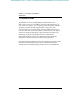
efesotomasyon.com - Control Techniques,emerson,saftronics -ac drive-servo motor Chapter 1 - Receiving & Installation Specifications Power Supply Output Characteristics Power Supply Output Characteristics 1.2 SPECIFICATIONS FP5/GP5 Inverter Model CIMR-P5U Motor Output (HP) * Capacity (kVA) Rated Output Current (A)-VT** Rated Output Current (A)-CT** 20P4 20P7 21P5 22P2 23P7 25P5 27P5 2011 2015 0.5 1 2 3 5 7.5 10 20 25 1.2 2.3 3.0 4.2 6.7 9.5 13 19 24 - 3.2 6 8 11 17.5 27 36 54 68 - 3.
efesotomasyon.com - Control Techniques,emerson,saftronics -ac drive-servo motor Control Characteristics Chapter 1 - Receiving & Installation Specifications Control Method Frequency Control Range Frequency Accuracy Frequency Setting Resolution Output Frequency Resolution Frequency Setting Accel/Decel Time Protective Functions Braking Torque No.
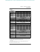
efesotomasyon.com - Control Techniques,emerson,saftronics -ac drive-servo motor Chapter 1 - Receiving & Installation Specifications FP5/GP5 Output Characteristics Inverter Model CIMR-P5U 2018 2022 2030 2037 2045 2055 2075 Motor Output (HP) * 30 40 50 60 75 100 125 Capacity (kVA) 30 37 50 61 70 85 Rated Output Current (A) - VT ** 80 104 130 160 192 248 312 Rated Output Current (A) - CT ** 64 83 3-Phase, 200/208/220/230V (Proportional to input voltage) Max.
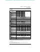
efesotomasyon.com - Control Techniques,emerson,saftronics -ac drive-servo motor Chapter 1 - Receiving & Installation Specifications Control Method Frequency Control Range Control Characteristics Frequency Accuracy Digital Operator Reference: 0.1Hz, Analog Reference: 0.06Hz (@60Hz) Output Frequency Resolution 0.01 Hz Frequency Setting 0 to +10VDC (20kΩ), 4-20mA (250Ω) Accel/Decel Time 0.0 to 3600.0 sec. (Accel/Decel time setting independently: 0.1 sec ) No.
efesotomasyon.com - Control Techniques,emerson,saftronics -ac drive-servo motor Chapter 1 - Receiving & Installation Preliminary Inspection 1.3 PRELIMINARY INSPECTION Receiving After unpacking the FP5/GP5: · Verify that the part numbers on the drive nameplate match the numbers on your purchase order or packing slip. · Check the unit for physical damage which may have occurred during shipping. If any part of the drive is missing or damaged, notify the carrier and your Saftronics representative immediately.
efesotomasyon.
efesotomasyon.com - Control Techniques,emerson,saftronics -ac drive-servo motor Chapter 1 - Receiving & Installation Mounting 1.4 MOUNTING ! CAUTION PRECAUTIONS 1) When preparing to mount the FP5/GP5, lift it by its base. Never lift it by the front cover. 2) Mount the inverter onto nonflammable material. 3) The FP5/GP5 generates heat. For the most effective cooling possible, mount it vertically. For more details, refer to “Dimensions/ Heat Loss” on pages 15 & 16 and “Clearances” on page 17.
efesotomasyon.com - Control Techniques,emerson,saftronics -ac drive-servo motor Chapter 1 - Receiving & Installation Mounting Removing and Replacing the Digital Operator To remove the digital operator from the front cover, push the operator lever in the direction shown by arrow 1 and lift the digital operator in the direction shown by arrow 2 (see Figure 4).
efesotomasyon.com - Control Techniques,emerson,saftronics -ac drive-servo motor Chapter 1 - Receiving & Installation Mounting Dimensions/Heat Loss Open Chassis Type (IP00) Model Voltage CIMR -P5U Open Chassis Dimensions in inches (mm) W H D W1 H1 H2 Mass lbs (kg) 5.51 (140) 11.02 (280) 6.30 (160) 4.96 (126) 10.47 (266) 0.28 (7) 6.5 (3) 20P4 20P7 21P5 22P2 23P7 25P5 230V 27P5 2011 2015 2018 2022 2030 2037 2045 5.51 (140) 11.02 (280) 7.09 (180) 4.96 (126) 10.47 (266) 0.28 (7) 10 (4.
efesotomasyon.com - Control Techniques,emerson,saftronics -ac drive-servo motor Chapter 1 - Receiving & Installation Mounting Enclosed Type (NEMA 1, IP20) Model Voltage (CIMRP5U) 20P4 20P7 21P5 22P2 23P7 230V 25P5 27P5 2011 2015 2018 2022 2030 2037 2045 2055 460V 2075 40P4 40P7 41P5 42P2 43P7 44P0 45P5 47P5 4011 4015 4018 4022 4030 4037 4045 4055 4075 4110 4160 16 NEMA 1 Dimensions in inches (mm) W H D W1 H1 H2 Mass lbs (kg) 5.51 (140) 11.02 (280) 6.30 (160) 4.96 (126) 10.47 (266) 0.
efesotomasyon.com - Control Techniques,emerson,saftronics -ac drive-servo motor H2 W1 W H H1 Chapter 1 - Receiving & Installation Mounting D Front View Side View Figure 7 FP5/GP5 Dimension Diagram Clearances When mounting the FP5/GP5, allow sufficient clearances for effective cooling as shown below: 1.97in (50mm) Air 4.72in (120mm) 1.18in (30mm) 1.97in (50mm) 4.
efesotomasyon.com - Control Techniques,emerson,saftronics -ac drive-servo motor Chapter 1 - Receiving & Installation Wiring 1.5 WIRING ! CAUTION PRECAUTIONS 1) Do not connect or disconnect wiring, or perform signal checks while the power supply is turned ON. 2) Connect the power supply wiring to terminals L1, L2 and L3 on the main circuit input section. DO NOT connect the power supply wiring to output terminals T1, T2 and T3.
efesotomasyon.
efesotomasyon.
efesotomasyon.com - Control Techniques,emerson,saftronics -ac drive-servo motor Chapter 1 - Receiving & Installation Wiring Main Circuit Wiring Input Wiring · Molded-Case Circuit Breaker (MCCB) Be sure to connect MCCBs or fuses between the AC main circuit power supply and FP5/GP5 input terminals L1, L2 and L3, to protect the power supply wiring. · Ground Fault Interrupter When connecting a ground fault interrupter to input terminals L1, L2 and L3, select one that is not affected by high frequency.
efesotomasyon.com - Control Techniques,emerson,saftronics -ac drive-servo motor Chapter 1 - Receiving & Installation Wiring · Surge Suppressor For inductive loads (i.e. magnetic contactors, magnetic relays, magnetic valves, solenoids, magnetic brakes, etc.) connected near the inverter, use a surge suppressor across the coils to limit the transients on the supply lines. Output Wiring · Motor Connection Connect motor lead wires to output terminals T1, T2 and T3.
efesotomasyon.com - Control Techniques,emerson,saftronics -ac drive-servo motor Chapter 1 - Receiving & Installation Wiring Grounding · Ground Resistance 230V class: 100Ω or less, 460V class: 10Ω or less. · Never ground the FP5/GP5 in common with welding machines, motors, or other high-current electrical equipment. Run all ground wiring in a separate conduit. · Use ground wiring as specified in “Wire and Terminal Screw Sizes” on page 25, and keep the length as short as possible.
efesotomasyon.com - Control Techniques,emerson,saftronics -ac drive-servo motor Chapter 1 - Receiving & Installation Wiring Terminal Functions 230V Class Terminal Functions Model CIMR-P5U Nominal Motor Output L1 L2 L3 L11 L21 L31 T1 T2 T3 B1 B2 ⊕1 ⊕2 ⊕3 20P4 to 27P5 0.
efesotomasyon.
efesotomasyon.
efesotomasyon.com - Control Techniques,emerson,saftronics -ac drive-servo motor Chapter 1 - Receiving & Installation Wiring JST Closed Loop Connectors Wire Size * AWG mm2 20 0.5 18 0.75 16 1.25 14 2 12 - 10 3.5 - 5.5 8 8 6 14 4 22 3-2 30 - 38 1 - 1/0 50 - 60 3/0 4/0 4/0 300MCM 400MCM 80 100 100 150 200 650MCM 325 Terminal Screw JST Closed-Loop Connectors (Lugs) Max. Torque lb-in (N·m) M3.5 M4 M3.5 M4 M3.5 M4 M3.5 M4 M5 M6 M8 M4 M5 M6 M8 M5 M6 M8 M6 M8 M6 M8 M8 M8 M10 1.25 - 3.
efesotomasyon.com - Control Techniques,emerson,saftronics -ac drive-servo motor Chapter 1 - Receiving & Installation Wiring Control Circuit Wiring The following table outlines the functions of the control circuit terminals.
efesotomasyon.com - Control Techniques,emerson,saftronics -ac drive-servo motor Chapter 2 - Operation - CHAPTER 2 - OPERATION Section 2 2.1 2.2 2.3 2.4 Description Page OPERATION Precautions. . . . . . . . . . . . . . . . . . . . . . . . . . . . . . . . . . . . 30 TRIAL OPERATION . . . . . . . . . . . . . . . . . . . . . . . . . . . . . . . . 31 Digital Operator Display at Power-up . . . . . . . . . . . . . . 31 Operation Checkpoints . . . . . . . . . . . . . . . . . . . . . . . . . .
efesotomasyon.com - Control Techniques,emerson,saftronics -ac drive-servo motor Chapter 2 - Operation Precautions ! WARNING PRECAUTIONS 1) Only turn ON the input power supply after replacing the front cover. Do not remove the cover while the inverter is powered up. 2) When the retry function (n060) is selected, do not approach the inverter or the load, since it may restart suddenly after being stopped.
efesotomasyon.com - Control Techniques,emerson,saftronics -ac drive-servo motor Chapter 2 - Operation Trial Operation 2.1 TRIAL OPERATION To ensure safety, prior to initial operation, disconnect the machine coupling so that the motor is isolated from the machine. If initial operation must be performed while the motor is still coupled to the machine, use great care to avoid potentially hazardous conditions. Check the following items before a trial run: · · · · · Wiring and terminal connections are proper.
efesotomasyon.com - Control Techniques,emerson,saftronics -ac drive-servo motor Chapter 2 - Operation Trial Operation Operation Checkpoints: · Motor rotates smoothly. · Motor rotates in the correct direction. · Motor has no abnormal vibration and is not noisy. · Acceleration and deceleration are smooth. · Unit is not overloaded. · Status indicator LEDs and digital operator display are correct. Basic Operation The inverter will operate after receiving a frequency reference.
efesotomasyon.com - Control Techniques,emerson,saftronics -ac drive-servo motor Chapter 2 - Operation Trial Operation Typical Operation Example by Digital Operator (JVOP-130P) Description Key Sequence (1) Power ON · Displays frequency reference value. Operation Condition Setting · Select LOCAL mode. (2) Frequency Setting · Change frequency reference value. Digital Operator Display REMOTE LED (SEQ, REF) ON Frequency Ref 0.
efesotomasyon.com - Control Techniques,emerson,saftronics -ac drive-servo motor Chapter 2 - Operation Trial Operation Operation by Control Circuit Terminal Signal The diagram below shows a typical operation pattern using the control circuit terminal signals.
efesotomasyon.com - Control Techniques,emerson,saftronics -ac drive-servo motor Chapter 2 - Operation Digital Operator Display 2.2 DIGITAL OPERATOR DISPLAY All functions of the FP5/GP5 are accessed using the JVOP-130P Digital Operator. Below are descriptions of the display and keypad sections. DRIVE FWD REV SEQ REMOTE REF Frequency Ref 0.
efesotomasyon.com - Control Techniques,emerson,saftronics -ac drive-servo motor Chapter 2 - Operation LED Description 2.3 LED DESCRIPTION Simple operation of the FP5/GP5 is possible, by using the quick-start displays. Quick-Start Displays (Example of CIMR-P5U23P7) Description Key Sequence Digital Operator Display Remarks Power ON 36 Frequency reference setting/monitoring DSPL Frequency Ref 0.0 Hz Output frequency monitor DSPL Output Freq 0.0 Hz Output current monitor DSPL Output Amps 0.
efesotomasyon.com - Control Techniques,emerson,saftronics -ac drive-servo motor Chapter 2 - Operation Operation Mode Selection 2.4 OPERATION MODE SELECTION (n002, Oper Mode Select) The FP5/GP5 has two operation modes: LOCAL and REMOTE (see table below for description). These two modes can be selected by the digital operator “LOCAL/REMOTE” key only when operation is stopped. The operation mode selected can be verified by observing the SEQ and REF LEDs on the digital operator (as shown below).
efesotomasyon.com - Control Techniques,emerson,saftronics -ac drive-servo motor This page intentionally left blank.
efesotomasyon.com - Control Techniques,emerson,saftronics -ac drive-servo motor Chapter 3 - Programming Features - CHAPTER 3 - PROGRAMMING FEATURES Section Description Page 3 PROGRAMMING FEATURES 3.1 3.2 3.3 41 FP5/GP5 PARAMETERS (n001~n116) . . . . . . . . . . . PARAMETER SET-UP & INITIALIZATION . . . . . . . . . . . . . . . 49 FP5/GP5 OPERATION . . . . . . . . . . . . . . . . . . . . . . . . 50 Accel/decel time adjustment . . . . . . . . . . . . . . . . . . . . . . 50 Automatic fault retry . . .
efesotomasyon.com - Control Techniques,emerson,saftronics -ac drive-servo motor Chapter 3 - Programming Features 3.4 40 Stopping method . . . . . . . . . . . . . . . . . . . . . . . . . . . . . . . 70 Torque adjustment. . . . . . . . . . . . . . . . . . . . . . . . . . . . . . 72 Torque detection . . . . . . . . . . . . . . . . . . . . . . . . . . . . . . . 73 Tripless operation . . . . . . . . . . . . . . . . . . . . . . . . . . . . . . 74 V/f pattern adjustment . . . . . . . . . . . . . . . . . . . .
efesotomasyon.com - Control Techniques,emerson,saftronics -ac drive-servo motor Chapter 3 - Programming Features FP5/GP5 Parameters 3.1 FP5/GP5 Parameters (n001~n116) No. Function Name (LCD Operator Display) Description Factory User Ref.
efesotomasyon.com - Control Techniques,emerson,saftronics -ac drive-servo motor Chapter 3 - Programming Features FP5/GP5 Parameters No. Function Name (LCD Operator Display) Description n014 Mid. output frequency (Mid Frequency) Unit: 0.1Hz Setting range: 0.1~399.9Hz n015 Mid. frequency voltage (Mid Voltage) Factory User Ref. Default Setting Page 3Hz 76 Unit: 0.1V Setting range: 0.1~255.0V (510V for 460V units) 17.2V (34.4V) 76 n016 Minimum output frequency (Min Frequency) Unit: 0.
efesotomasyon.com - Control Techniques,emerson,saftronics -ac drive-servo motor Chapter 3 - Programming Features FP5/GP5 Parameters No. Function Name (LCD Operator Display) n034 Motor thermal protection (Motor OL Sel) n035 Stop method selection OH1- for inverter overheat pre-alarm (OH1 Stop Method) n036 Multi-function input selection 1 (Terminal S2 Sel) FP5/GP5 User’s Manual Description LED Setting Factory User Ref.
efesotomasyon.com - Control Techniques,emerson,saftronics -ac drive-servo motor Chapter 3 - Programming Features FP5/GP5 Parameters No. Function Name (LCD Operator Display) Description Factory User Ref. Default Setting Page n037 Multi-function input 2 (Terminal S3 Sel) Set items are same as n036. (When n036=”FWD/REV Cmd (3W), “In Use By Other” is displayed, and setting is prohibited) Ext Fault (NO) 78 n038 Multi-function input 3 (Terminal S4 Sel) Set items are same as n036.
efesotomasyon.com - Control Techniques,emerson,saftronics -ac drive-servo motor Chapter 3 - Programming Features FP5/GP5 Parameters No. Function Name (LCD Operator Display) Description Factory User Ref.
efesotomasyon.com - Control Techniques,emerson,saftronics -ac drive-servo motor Chapter 3 - Programming Features FP5/GP5 Parameters No. Function Name (LCD Operator Display) n065 Elapsed timer selection (Elapsed Timer) Description LED Setting 0 1 Factory User Ref.
efesotomasyon.com - Control Techniques,emerson,saftronics -ac drive-servo motor Chapter 3 - Programming Features FP5/GP5 Parameters No. Function Name (LCD Operator Display) n078 Over/Undertorque detection level OL3 (Torq Det Level) Description Factory User Ref. Default Setting Page 160% 74 n079 Over/Undertorque detec- Unit: 0.1s tion delay time OL3 Setting range: 0.1~10.0s (Torq Det Time) 0.1s 74 n080 On-delay timer (On-Delay Timer) Unit: 0.1s Setting range: 0.0~25.5s 0.
efesotomasyon.com - Control Techniques,emerson,saftronics -ac drive-servo motor Chapter 3 - Programming Features Parameter Set-up & Initialization No. Function Name (LCD Operator Display) Description Factory User Ref. Default Setting Page n096 Energy saving selection (Energy Save Sel) LED Setting 0 1 n097 Energy saving gain K2 (Energy Save Gain) Unit: 0.01 Setting range: 0.00~655.
efesotomasyon.com - Control Techniques,emerson,saftronics -ac drive-servo motor Chapter 3 - Programming Features FP5/GP5 Operation No. Function Name (LCD Operator Display) n112 Low frequency OL start point (Low Freq OL2 Start) n113 0Hz continuous operation level (OL2_Level_@_0 Hz) n114 Not used n115 kVA selection (Inverter kVA Sel) n116 CT / VT selection (CT / VT Selection) Description Factory User Ref. Default Setting Page Unit: 0.1Hz Setting range: 0.0 ~ 10.0Hz 6.
efesotomasyon.com - Control Techniques,emerson,saftronics -ac drive-servo motor Chapter 3 - Programming Features FP5/GP5 Operation 3.
efesotomasyon.com - Control Techniques,emerson,saftronics -ac drive-servo motor Chapter 3 - Programming Features FP5/GP5 Operation Automatic Fault Retry (n060, Num of Restarts) After a fault occurs, the inverter can automatically restart. The number of retry attempts can be set up to 10 times via parameter n060.
efesotomasyon.com - Control Techniques,emerson,saftronics -ac drive-servo motor Chapter 3 - Programming Features FP5/GP5 Operation fc = carrier frequency fc = carrier frequency 2.5kHz 1.0kHz 2.5kHz 1.0kHz fc = 12 fout 83.3Hz 208.3Hz n054 = “Synchronous 1” fout fc = 24 fout 41.6Hz 104.1Hz n054 = “Synchronous 2” fout fc = carrier frequency 2.5kHz 1.0kHz fc = 36 fout 27.7Hz 69.
efesotomasyon.com - Control Techniques,emerson,saftronics -ac drive-servo motor Chapter 3 - Programming Features FP5/GP5 Operation Motor Current n073 Time Output Frequency Time * * Holds the output frequency to limit the load current.
efesotomasyon.com - Control Techniques,emerson,saftronics -ac drive-servo motor Chapter 3 - Programming Features FP5/GP5 Operation · Stall prevention during deceleration (n072, StallP Decel Sel) To prevent overvoltage during deceleration, the inverter automatically extends the deceleration time according to the value of main circuit DC voltage. When using an optional braking resistor for the FP5/GP5, set parameter n072 to”0”.
efesotomasyon.com - Control Techniques,emerson,saftronics -ac drive-servo motor Chapter 3 - Programming Features FP5/GP5 Operation · DC injection Braking Time at Start (n070) DC injection braking time at start can be set in increments of 0.1 second. When parameter n070 is set to “0”, DC injection braking at starting is disabled. n016 Min.
efesotomasyon.com - Control Techniques,emerson,saftronics -ac drive-servo motor Chapter 3 - Programming Features FP5/GP5 Operation limit, this lower limit value is output as the voltage reference value. The lower limit value is set in order to prevent stalling at light loads. Set voltage limits at 6Hz and 60Hz; a value obtained by linear interpolation should be used to set any limit values other than at 6Hz or 60Hz. Setting is made as a percentage of motor rated voltage.
efesotomasyon.com - Control Techniques,emerson,saftronics -ac drive-servo motor Chapter 3 - Programming Features FP5/GP5Operation Frequency Agree Set Point (n075, Freq Det Level) When multi-function contact output selections n041 or n042 are set to “Freq Det 1” or “Freq Det 2”, frequency detection is enabled. This function is activated when the output frequency is above or below the frequency agree set point (n075). · Output frequency ≤ Frequency agree set point Set n041 or n042 to “Freq Det 1”.
efesotomasyon.com - Control Techniques,emerson,saftronics -ac drive-servo motor Chapter 3 - Programming Features FP5/GP5 Operation Frequency Meter or Ammeter (n052, Terminal AM Sel) This parameter selects whether the signal (on terminals AM and AC) is proportional to output frequency, output current, output power, or DC bus voltage for external monitoring. Setting Output Freq Output Amps Output kWatts DC Bus Voltage Analog Monitor Output Selection Output frequency (10V/max.
efesotomasyon.com - Control Techniques,emerson,saftronics -ac drive-servo motor Chapter 3 - Programming Features FP5/GP5 Operation · Terminal FV Gain (n048, Terminal FV Gain) The analog input voltage value for the maximum output frequency (n011) can be set in units of 1%, from 0 to 200%. Factory setting: 100% · Terminal FV Bias (n049, Terminal FV Bias) The frequency reference that is generated when the analog input is 0V can be set in units of 1%, from -100% to 100%.
efesotomasyon.com - Control Techniques,emerson,saftronics -ac drive-servo motor Chapter 3 - Programming Features FP5/GP5 Operation To operate the inverter with a frequency reference of 50% to 100% at a 0 to 10V input: Max. Output Frequency (100%) 50% 0V 10V Figure 31 Frequency Signal Adjustment Example - 0 to 10V input Gain: Parameter n048 = “100” Bias: Parameter n049 = “50” Jog Operation Multi-function inputs (Terminals S2 to S6) can be programmed to function as a jog reference selection.
efesotomasyon.com - Control Techniques,emerson,saftronics -ac drive-servo motor Chapter 3 - Programming Features FP5/GP5 Operation MODBUS Communication The FP5/GP5 can perform serial transmission by using a programmable controller (PLC) and MODBUS communication. MODBUS is composed of one master PLC and 1 to 31 (maximum) slave inverters. In signal transmission between master and slave units, the master unit always starts transmission and the slave units respond to it.
efesotomasyon.com - Control Techniques,emerson,saftronics -ac drive-servo motor Chapter 3 - Programming Features FP5/GP5 Operation · MODBUS Frequency Reference Unit (n103, MODBUS Fref Unit) The frequency reference units from the PLC and in the frequency reference and output frequency monitors (by communication) are set with parameter n103. The output frequency resolution of the FP5/GP5 is 0.1Hz. Even if the frequency reference unit is changed to 0.
efesotomasyon.com - Control Techniques,emerson,saftronics -ac drive-servo motor Chapter 3 - Programming Features FP5/GP5 Operation · General-purpose and Blower-cooled Motors Induction motors are classified as general-purpose or blower-cooled motors, based on their cooling capabilities. Hence, the motor overload detection function operates differently for each of these two motor types.
efesotomasyon.com - Control Techniques,emerson,saftronics -ac drive-servo motor Chapter 3 - Programming Features FP5/GP5 Operation Multi-Step Speed Selection This function allows the programming of up to 4 preset speeds, through multi-function contact input selections. 4-step speed selection n002 = “SEQ=X REF=OPR”, where “X” can be TRM, OPR, or COM n024 = 30.0Hz (factory default = 0.0Hz) n025 = 40.0Hz (factory default = 0.0Hz) n026 = 50.0Hz (factory default = 0.0Hz) n027 = 60.0Hz (factory default = 0.
efesotomasyon.com - Control Techniques,emerson,saftronics -ac drive-servo motor Chapter 3 - Programming Features FP5/GP5 Operation Phase Loss Protection · Input Phase Loss Detection (n083, In Ph Loss Lvl) The input phase loss detection circuit monitors the DC bus current ripple and activates when one of the input phases are lost. The detection circuit calculates the maximum and minimum values of the DC bus voltage in 1.
efesotomasyon.com - Control Techniques,emerson,saftronics -ac drive-servo motor Chapter 3 - Programming Features FP5/GP5 Operation PID Control To enable PID control, set PID selection (n084) to “Enabled”, according to the description below. LED Setting LCD Setting 0 Disabled 1 Enabled D=Fdbk 2 Enabled D=Fdfwd 3 Enabled Rev Fdbk Description PID disabled (factory default) PID enabled (deviation is D-controlled.
efesotomasyon.com - Control Techniques,emerson,saftronics -ac drive-servo motor Chapter 3 - Programming Features FP5/GP5 Operation + Intended Value (Deviation) - n085 Feedback Calibration Gain P 0 I n084 n087 1 Detected Value D D + + n088 n088 2 Limit n089 1 + + + ±109% Limit Frequency Reference Sleep Function n094, n095 1 or 3 1, 2, or 3 n084 Inverted Characteristic Enabled 2 3 Z-1 n093 0 n084 Figure 35a PID Control Block Diagram Notes: 1) 2) 3. 4. 5.
efesotomasyon.com - Control Techniques,emerson,saftronics -ac drive-servo motor Chapter 3 - Programming Features FP5/GP5 Operation Reverse Run Prohibit (n006, Reverse Oper) A “reverse run disabled” setting does not accept a reverse run command from the control circuit terminal or the digital operator. This setting is used in applications where a reverse run command can cause problems.
efesotomasyon.com - Control Techniques,emerson,saftronics -ac drive-servo motor Chapter 3 - Programming Features FP5/GP5 Operation The following figure shows FWD/REV run switching during deceleration to stop. FWD Run Command REV Run Command Acceleration Output Frequency Min. Output Frequency n016 Deceleration DC Injection Braking Time at Stop n069 Min.
efesotomasyon.com - Control Techniques,emerson,saftronics -ac drive-servo motor Chapter 3 - Programming Features FP5/GP5 Operation Stopping Method (n004, Stopping Method) This function selects the stopping method suitable for the particular application.
efesotomasyon.
efesotomasyon.com - Control Techniques,emerson,saftronics -ac drive-servo motor Chapter 3 - Programming Features FP5/GP5 Operation Torque Adjustment (n071, Torq Comp Gain) Motor torque can be adjusted by changing the V/f pattern (n010) or by adjusting the torque compensation gain (n071). For details on setting the V/f pattern, see “V/f Pattern Adjustment”, on page 75. · Full-range Automatic Torque Boost The motor torque requirement changes according to load conditions.
efesotomasyon.com - Control Techniques,emerson,saftronics -ac drive-servo motor Chapter 3 - Programming Features FP5/GP5 Operation Torque Detection The over/undertorque detection circuit will activate when the motor load causes the motor current to go above or below torque detection level (n078) respectively. When the over/undertorque condition is detected, alarm signals are sent to multi-function output terminals MA, MB and/or M1.
efesotomasyon.
efesotomasyon.com - Control Techniques,emerson,saftronics -ac drive-servo motor Chapter 3 - Programming Features FP5/GP5 Operation · DC Injection Braking at Start (n068, DCInj Current; n070, DCInj Time@Start) This function restarts a coasting motor after first applying it with DC injection braking. DC injection braking time at start (n070) is set in units of 0.1 second. DC injection braking current is set in parameter n068 in units of 1%.
efesotomasyon.com - Control Techniques,emerson,saftronics -ac drive-servo motor Chapter 3 - Programming Features Inputs & Outputs Be sure to satisfy the following conditions for setting parameters n011 to n017: n016 ≤ n014 < n013 ≤ n011 Voltage n012 n015 n017 0 n016 n014 n013 n011 Frequency Figure 46 Custom V/f Pattern Setting Parameter No. n011 n012 n013 n014 n015 n016 n017 Name Maximum output frequency Maximum voltage Maximum voltage output frequency (base frequency) Mid. output frequency Mid.
efesotomasyon.com - Control Techniques,emerson,saftronics -ac drive-servo motor Chapter 3 - Programming Features Inputs & Outputs Slip Compensation The slip compensation feature allows better speed regulation to be obtained by adjusting the output frequency according to the changing load. This feature compensates for the slip of the motor. Slip Compensation Gain (n107, Slip Comp Gain) This parameter is used to input the slip of the motor. The setting is entered as a percent of base frequency (n013).
efesotomasyon.com - Control Techniques,emerson,saftronics -ac drive-servo motor Chapter 3 - Programming Features Inputs & Outputs 3.4 INPUTS & OUTPUTS Multi-function Input Signals (n036 to n040) Multi-function contact input terminal S2 to S6 functions can be changed when necessary by setting parameters n036 to n040, respectively. None of these parameters can receive a setting common with the other (no duplication).
efesotomasyon.
efesotomasyon.com - Control Techniques,emerson,saftronics -ac drive-servo motor Chapter 3 - Programming Features Inputs & Outputs Example: Set n002 to “SEQ=TRM REF=TRM”. Open: Frequency reference from control circuit terminals FV & FI, and run command from control circuit terminals S1 and S2. Closed: Frequency reference and run command from serial communication.
efesotomasyon.com - Control Techniques,emerson,saftronics -ac drive-servo motor Chapter 3 - Programming Features Inputs & Outputs · Up/Down Command (setting: n040 = “Up/Down Control”) With the FWD (REV) run command entered, a change in frequency is performed by inputting the Up or Down commands to control circuit terminals S5 and S6, so that operation can be performed at the desired speed.
efesotomasyon.com - Control Techniques,emerson,saftronics -ac drive-servo motor Chapter 3 - Programming Features Inputs & Outputs Analog Input Signals · Master Analog Input Selection (n043, Analog Input Sel) To input the master frequency reference from the control circuit terminal, use terminal FV (0 to 10V) or terminal FI (4 to 20mA), by setting parameter n043.
efesotomasyon.com - Control Techniques,emerson,saftronics -ac drive-servo motor Multi-function Output Signals (n041, Terminal MA Sel; n042, Terminal M1 Sel) Multi-function output terminal MA, MB and M1 functions can be changed when necessary by setting parameters n041 and n042. · Terminal MA and MB functions: set via n041 · Terminal M1 functions: set via n042 Factory defaults: n041 = “Fault”, n042 = “During Running” Multi-function Output Signals LED Setting LCD Setting Description Ref.
efesotomasyon.com - Control Techniques,emerson,saftronics -ac drive-servo motor Chapter 3 - Programming Features Frequency Agree (setting: “At Speed”) See Figure 51 below for an example of selecting the frequency agree signal as the function of output terminals MA, MB or M1.
efesotomasyon.com - Control Techniques,emerson,saftronics -ac drive-servo motor Chapter 4 - Diagnostics - CHAPTER 4 - DIAGNOSTICS Section 4 4.1 4.2 Description Page DIAGNOSTICS Precautions. . . . . . . . . . . . . . . . . . . . . . . . . . . . . . . . . . . . 86 MAINTENANCE & INSPECTION . . . . . . . . . . . . . . . . . . . . . . 87 Periodic Inspection . . . . . . . . . . . . . . . . . . . . . . . . . . . . . 87 Parts Replacement Schedule. . . . . . . . . . . . . . . . . . . . . .
efesotomasyon.com - Control Techniques,emerson,saftronics -ac drive-servo motor Chapter 4 - Diagnostics Precautions ! WARNING PRECAUTIONS 1) Never touch high voltage terminals in the inverter. 2) Replace all protective covers before powering up the inverter. When removing the cover, be sure to shut OFF the power supply to the inverter. 3) Perform maintenance or inspection only after verifying that the charge LED has gone OFF, after the main circuit power supply is turned OFF.
efesotomasyon.com - Control Techniques,emerson,saftronics -ac drive-servo motor Chapter 4 - Diagnostics Maintenance & Inspection 4.1 MAINTENANCE & INSPECTION This section describes basic maintenance and inspection procedures for the FP5/GP5. Periodic Inspection The FP5/GP5 will function longer if it is kept clean, cool and dry, and if all precautions highlighted in this manual are observed.
efesotomasyon.com - Control Techniques,emerson,saftronics -ac drive-servo motor Chapter 4 - Diagnostics Alarm & Fault Displays 4.2 ALARM & FAULT DISPLAYS This section describes the alarm and fault displays, explanations for fault conditions, and corrective actions to be taken if the FP5/GP5 malfunctions. Alarm Display Unlike faults, alarms do not activate fault contact outputs. After the cause of the alarm is corrected, the inverter returns to its former operation status automatically.
efesotomasyon.com - Control Techniques,emerson,saftronics -ac drive-servo motor Chapter 4 - Diagnostics Alarm & Fault Displays Fault Display When the FP5/GP5 detects a fault, the fault is displayed on the digital operator and a fault contact output is activated after which the motor coasts to a stop. Check the causes listed in the table below and take the corresponding corrective actions.
efesotomasyon.com - Control Techniques,emerson,saftronics -ac drive-servo motor Chapter 4 - Diagnostics Alarm & Fault Displays LCD OperatorFault Display *oH1 Name Overheat Heatsink overheat (OH1) 1 oH2 Overheat Heatsink overheat (OH2) 2 oL1 Overload 1 oL2 Overload 2 Description Corrective Action The transistor heatsink temperature exceeded the allowable value (Fin temperature > OH1 detection level). Check the fan and ambient temperature.
efesotomasyon.
efesotomasyon.com - Control Techniques,emerson,saftronics -ac drive-servo motor Appendix Contents Motor Faults If a motor fault occurs, follow the checkpoints listed in the table below and take the corresponding corrective actions. If taking the corrective actions described does not solve the problem, contact your Saftronics representative immediately. Motor Faults and Corrective Actions Fault Check Point Corrective Action · Turn ON power supply.
efesotomasyon.com - Control Techniques,emerson,saftronics -ac drive-servo motor Appendix Table of Contents APPENDIX Section Description Page A APPENDIX A-1 A-2 A-3 BRAKING CONNECTION DIAGRAMS . . . . . . . . . . . . . . . . . . 94 DIGITAL OPERATOR MONITOR DISPLAY . . . . . . . . . . . . . . 95 CE CONFORMANCE . . . . . . . . . . . . . . . . . . . . . . . . . . . . . . .
efesotomasyon.
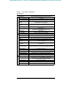
efesotomasyon.com - Control Techniques,emerson,saftronics -ac drive-servo motor Appendix A-2 Digital Operator Monitor Display A-2 DIGITAL OPERATOR MONITOR DISPLAY The following table describes the contents of the digital operator monitor display. Digital Operator Monitor Display Name (LCD Operator Display) Frequency Reference (Frequency Ref) Output Frequency (Output Freq) Output Current (Output Amps) Output Power (Output Power) Description · · · · Frequency reference can be monitored/set.
efesotomasyon.com - Control Techniques,emerson,saftronics -ac drive-servo motor Appendix A-2 Digital Operator Monitor Display Name (LCD Operator Display) Description U-09 Last 4 faults are displayed. U-10 Last 4 digits of software revision number are displayed.
efesotomasyon.
efesotomasyon.com - Control Techniques,emerson,saftronics -ac drive-servo motor Appendix A-3 CE Conformance CE CONFORMANCE - Electro-Magnetic Compatibility (EMC) Compliance In order to conform to EMC standards, exclusive-use methods are required for line filter application, cable shielding and inverter installation. An outline of the methods follows. The line filter and the inverter must be mounted on the same metal plate. The filter should be mounted as close to the inverter as practical.
efesotomasyon.com - Control Techniques,emerson,saftronics -ac drive-servo motor Appendix A-3 CE Conformance L3 L2 L1 GND Ground Bonds (Remove any paint) Line Power Inverter Filter Load L1L2 L3 UV W Cable Length: Max. 40cm Metal Plate Motor Cable: Max. 20m Ground Bonds (Remove any paint) IM Fig. 12 Installation of Line Filter and Inverter (Models FP5/GP5 40P4 to 4015) L3 L2 L1 GND Line Power Ground Bonds (Remove any paint) Inverter Filter Load L1L2 L3 UV W Cable Length: Max.
efesotomasyon.com - Control Techniques,emerson,saftronics -ac drive-servo motor Appendix A-3 CE Conformance Safety Warnings and Operating Information for Inverters Introduction Depending on their protection rating configuration, parts of inverters can have live, uninsulated and hot surfaces during operation. If housing components, the control unit or terminal covers are removed, incorrect installation and operation can lead to serious injuries and damage to other installations.
efesotomasyon.com - Control Techniques,emerson,saftronics -ac drive-servo motor Appendix A-3 CE Conformance EU Manufacturer’s Declaration Products Static inverter, series FP5/GP5 Scope Saftronics inverters are components (BDM* , defined by IEC 22G/21CDV) designed exclusively for installation in machines or systems (end products) by qualified re-users (e.g. mechanical engineering manufacturers). Responsibility As a component manufacturer we are responsible for the provision of installation instructions.