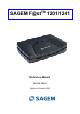
TM SAGEM F@st 1201/1241 Reference Manual 288 110 393-01 Edition of October 2006
Sagem Communication assiduously monitors technical developments and is constantly seeking to improve its products in order to let its clients take full advantage of them. It therefore reserves the right to modify its documentation accordingly without notice. All brands mentioned in this guide are registered by their respective owners: • SAGEM F@st™ is a registered brand of Sagem Communication. • SAGEM F@st™ is a registered brand of Sagem Communication.
How should the document be used? The present reference manual is organised into sections and annexes. These sections and annexes cover the following subjects.
Contents Pages Contents 0-3 to 0-6 1. Introduction 1-1 1.1 Presentation 1-2 1.2 Composition of router pack 1-4 1.3 Minimum prerequisite 1-5 2. Description and connection of router 2-1 2.1 Description 2.1.1 "Connectors" side view 2.1.2 "LEDs" view 2-2 2-3 2-4 2.2 Connecting the ports of your router 2.2.1 Connecting to a power socket 2.2.2 Connection of the ADSL cable to the router 2.2.3 Connecting to your computer 2.2.3.1 Connection of the USB interface of your router to your computer 2.
5.5 5.6 Status 5.5.1 Summary 5.5.2 Diagnostics Internet Connection 5-6 5-6 5-7 5-9 5.7 NAT 5.7.1 Port forwarding 5.7.2 DMZ Host 5-10 5-10 5-15 5.8 Advanced Setup 5.8.1 WAN 5.8.2 LAN 5.8.3 Security 5.8.3.1 Outgoing 5.8.3.2 Incoming 5.8.4 Routing 5.8.4.1 Default Gateway 5.8.4.2 Static Route 5.8.5 DNS 5.8.6 DSL 5-16 5-16 5-38 5-40 5-40 5-42 5-45 5-45 5-46 5-48 5-49 5.9 Advanced Status 5.9.1 WAN 5.9.2 Statistics 5.9.2.1 LAN 5.9.2.2 WAN 5.9.2.3 ATM 5.9.2.4 ADSL 5.9.3 Route 5.9.4 ARP 5.9.
. Updating the application 7-1 A. Annex A - Troubleshooting A-1 A.1 Checking the attribution of an IP address A.1.1 In Windows A.1.2 On a Mac (for example MacOS X) A-2 A-2 A-2 A.2 Front Face LEDs A-3 A.3 Supervising your router A-4 A.4 "Diagnostics" tool A-5 A.5 Interpreting the LEDs A.5.1 The "ADSL" LED blinks slowly A.5.2 All LEDs are off A-7 A-7 A-7 A.6 Reinitialising your router A-8 A.7 Re-establishing the factory configuration A-8 A.8 Offline mode A-9 B.
F. Annex F - Glossary F-1 G. Annex G - Connector Technology G-1 G.1 Pinouts of the "LINE" connector G-2 G.2 Pinouts of the "PWR" connector G-2 G.3 Pinouts of the "ETH" connector G-3 G.4 Pinouts of the "USB" connector G-4 SAGEM F@st™ 1201/1241 Reference Manual - 288110393-01 Page 0-6 Sagem Communication document.
1. Introduction This section covers ¾ presentation of the SAGEM F@stTM 1201/1241 equipment § 1.1 ¾ composition of the packaging § 1.2 ¾ required hardware and software § 1.3 SAGEM F@st™ 1201/1241 Reference Manual - 288110393-01 Sagem Communication document.
1 - Introduction 1.1 Presentation The present reference manual is dedicated to the SAGEM F@stTM 1201 and SAGEM F@stTM 1241 product ranges. These products are routers which give users, via an ADSL/ADSL2/ ADSL2+ network, broadband Internet access from their computer or their games console by various Ethernet (10 or 100 BASE-T) or USB interfaces. SAGEM F@stTM 1201 and SAGEM F@stTM 1241 products adapt the ADSL function respectively for POTS (UIT G.992.1/3/5 - Annex A) and for ISDN (UIT G.992.1/3/5 - Annex B).
1 - Introduction Its principal characteristics and functions are as follows: ¾ High-performance secure Bridge/Router with ADSL/ADSL2/ADSL2+ interface, ¾ User access: • 1 10/100BT Ethernet port, • 1 USB1.
1 - Introduction 1.2 Composition of router pack The router is supplied in a pack with the following contents: ¾ 1 SAGEM F@stTM 1201 or SAGEM F@stTM 1241, ¾ 1 mains adapter unit, ¾ 1 grey ADSL RJ11/RJ11 FDT line cord (length = 3 m), ¾ 1 yellow Ethernet RJ45/RJ45 linking cord (length = 1.75 m), ¾ 1 blue USB Type A male/Type B male cable (length = 1.5 m), ¾ 1 Quick Installation Guide, ¾ 1 Installation CD-ROM, ¾ microfilter(s) (option), ¾ 1 filter/splitter (option).
1 - Introduction The CD ROM contains: • the application for installing the USB interface. • the present Reference Manual (SAGEM F@st™ 1201/1241) in PDF format file. • the CE declaration of the chosen router. Incomplete or damaged supply. If on its receipt the equipment is damaged or incomplete, contact the Supplier of your router. 1.
1 - Introduction SAGEM F@st™ 1201/1241 Reference Manual - 288110393-01 Page 1-6 Sagem Communication document.
2. Description and connection of router This section covers ¾ the description of your router § 2.1 ¾ connecting the ports of your router § 2.2 ¾ connecting to a power socket § 2.2.1 ¾ connecting the line cable § 2.2.2 ¾ connecting your computer § 2.2.3 ¾ installation instructions § 2.3 SAGEM F@st™ 1201/1241 Reference Manual - 288110393-01 Sagem Communication document.
2 - Description and connection of router 2.1 Description Figure 2.1 gives an overview of a router SAGEM F@stTM 1201 or SAGEM F@stTM 1241. Figure 2.1 - Overview of case This case consists principally of a lid and a base in which a printed circuit equipped with electronic components is located. The front face has four display LEDs (cf.§ 2.1.2). The base has the LEDs ideograms, SAGEM's mark and logo or the operator's marking as well.
2 - Description and connection of your router 2.1.1 "Connectors" side view Marking Meaning LINE RJ11 connector - 6 pts. This grey connector is used for the connection to an ADSL line (WAN interface). USB Type B USB female connector. This blue connector is used for connection to a computer (USB interface). ETH RJ45 connector - 8 pts (10/100BASE-T Ethernet Interface). This yellow connector is is used for connection to a computer (10/100BASE-T ETH interface).
2 - Description and connection of router 2.1.2 "LEDs" view The different LEDs of the figure below are described in the following table: Marking Abbreviation PWR ADSL LAN Meaning Alarm LED (bicolour LED Green/Red): • lits green if power is present, • lits red in the case of failure detected at the time of starting.
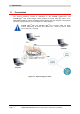
2 - Description and connection of your router 2.2 Connecting the ports of your router Figure 2.2 - Interconnection of ports of SAGEM F@stTM 1201/1241 SAGEM F@st™ 1201/1241 Reference Manual - 288110393-01 Sagem Communication document.
2 - Description and connection of router 2.2.1 Connecting to a power socket ¾ First connect the end of the mains cord, supplied with the equipment, to the PWR base of your router. ¾ Connect the mains adapter to a nearby mains wall socket. ¾ Set the "On/Off" switch to On. SAGEM F@st™ 1201/1241 Reference Manual - 288110393-01 Page 2-6 Sagem Communication document.
2 - Description and connection of your router 2.2.2 Connection of the ADSL cable to the router ¾ Connect an end of the supplied grey RJ11/RJ11 cable to the grey fixed connector marked LINE of your router. ¾ Connect the other end of this cable to the connector marked ADSL on the micro-filter connected to the RJ11 telephone wall socket of your home. SAGEM F@st™ 1201/1241 Reference Manual - 288110393-01 Sagem Communication document.
2 - Description and connection of router 2.2.3 Connecting to your computer Two connections may have to be made: ¾ Connection of the USB interface of your router to your computer. ¾ Connection of the Ethernet interface of your router to your computer. 2.2.3.1 Connection of the USB interface of your router to your computer This connection is made in all cases after installing the drivers of the USB interface (see section 3).
2 - Description and connection of your router 2.2.3.2 Connecting the Ethernet interface of your router to your computer ¾ Connect the end of the yellow Ethernet cable (RJ45/RJ45) supplied in the pack to the yellow Ethernet fixed connector marked ETH of your router, ¾ Connect the other end of the cable to your computer. SAGEM F@st™ 1201/1241 Reference Manual - 288110393-01 Sagem Communication document.
2 - Description and connection of router 2.3 Installation instructions Environment ¾ The router must be installed and used inside a building. ¾ The ambient temperature must not exceed 45°C. ¾ The router must not be exposed to direct strong sunlight nor to an intense heat source. ¾ The router must not be placed in an environment subject to vapour condensation. ¾ The router must not be exposed to water projections. ¾ The router unit must not be covered.
3. Installing and configuring the router This section covers ¾ installing your router with the network card of your computer (Ethernet). § 3.1 ¾ installing your router in the USB port of your computer. § 3.2 ¾ installing an additional computer. § 3.3 SAGEM F@st™ 1201/1241 Reference Manual - 288110393-01 Sagem Communication document.
3 - Installing and configuring the router Your router can be installed and configured with the following interfaces: ¾ Ethernet (ETH)(cf. § 3.1), ¾ USB (cf. § 3.2). Before installing your router, we recommend you uninstall every ADSL router. The installation procedure described below was undertaken in Windows® XP. Installation in other Windows operating systems® (98, ME and 2000) can be slightly different.
3 - Installing and configuring the router 2 The screen opposite appears. Carry out the operations described on the screen. Click button the installation. 3 to continue A screen enabling the type of installation to the chosen (first installation or installation of an additional computer) appears. For a first installation, we recommend that you check the button then click on the installation. 4 to continue The screen opposite appears.
3 - Installing and configuring the router 3.1 Installing and configuring your Router with the network card of your computer (Ethernet) The Ethernet fixed connector marked ETH of your router is designed for connecting your computers or wired Ethernet network equipment. It supports 10 Mbit/s and 100 Mbit/s transmission rates in Half or Full Duplex mode on a category 5 double twisted pair cable. This port is a RJ45 connector with wiring of the self-detecting MDI or MDI-x type.
3 - Installing and configuring the router 3 Connect the Ethernet cable as described on the screen. Click button the installation. to continue 4 The screen opposite appears and asks you to wait. 5 The screen opposite appears. Please wait during the diagnostics of the connection to the Router via an Ethernet cable. SAGEM F@st™ 1201/1241 Reference Manual - 288110393-01 Sagem Communication document.
3 - Installing and configuring the router 6 The screen opposite appears. Enter the connection identifier followed by the connection password. The latter are available from your subscription confirmation letter. Click button the installation. 7 to continue The screen opposite appears and asks you to wait during the successive diagnostics. The rotating orange arrows are replaced by a green check mark after each successful test. 8 The screen opposite appears.
3 - Installing and configuring the router 9 The "SAGEM" welcome screen appears. You can now use your Internet access. SAGEM F@st™ 1201/1241 Reference Manual - 288110393-01 Sagem Communication document.
3 - Installing and configuring the router 3.2 Installing and configuring your Router in the USB port of your computer The USB port of your router is of the USB 1.1 type allowing a maximum transmission rate of 12 Mbit/s. With this port, you can connect directly to a computer located at a type A USB input, using a USB cord (supplied with the equipment). The USB interface must in all cases be installed before the USB connector is connected.
3 - Installing and configuring the router 3 The screen opposite appears and asks you to wait. 4 Connect the USB cable as described on the screen. 5 The screen opposite appears. Please wait during the diagnostics of the connection to the Router via a USB cable. SAGEM F@st™ 1201/1241 Reference Manual - 288110393-01 Sagem Communication document.
3 - Installing and configuring the router 6 The screen opposite appears. Enter the connection identifier followed by the connection password. The latter are available from your subscription confirmation letter. Click button the installation. 7 to continue The screen opposite appears and asks you to wait during the successive diagnostics. The rotating orange arrows are replaced by a green check mark after each successful test. 8 The screen opposite appears.
3 - Installing and configuring the router 9 The "SAGEM" welcome screen appears. You can now use your Internet access. If you wish to install your router with another interface, you must imperatively uninstall your router. To do this: Select Start/All programs/SAGEM F@st™ 1201/Uninstall SAGEM F@st™ 1201/1241 Reference Manual - 288110393-01 Sagem Communication document.
3 - Installing and configuring the router 3.3 Installing and configuring an additional computer You have chosen to install an additional computer by clicking button ; you have then clicked button to continue the installation. 1 The screen opposite appears. This screen enables you to choose to which interface (Ethernet or USB) you wish to connect your router to your computer. Click "Use the Ethernet cable" (cf. § 3.1), Click "Use the Ethernet cable" (cf. § 3.
4. Configuration of network parameters This section covers ¾ configuring as a DHCP client Page 4-3 ¾ reading data of the DHCP server Page 4-4 ¾ reading data of the DHCP client Page 4-6 SAGEM F@st™ 1201/1241 Reference Manual - 288110393-01 Sagem Communication document.
4 - Configuration of network parameters The aim of this section is: 1) to configure your computer so that it is able to communicate with your router. 2) and to display the "Networks" parameters of your router. Your router implements the DHCP (Dynamic Host Configuration Protocol) server, relay and client functions in accordance with RFC 2131 and RFC 3132, whereas the computer connected directly to the router or via a local network by its LAN interface implements only the DHCP client function.
4 - Configuration of network parameters 1) Configuring as a DHCP client In Windows XP • Click on Start/Control Panel/Network Connections. • Right-click on the network which you are using, and then select Properties. • Click on protocol TCP/IP of the network card, and then click on Properties. The screen opposite appears. • Select the general tab, then the command "Obtain an IP address automatically" and the command "Obtain the addresses of the DNS servers automatically".
4 - Configuration of network parameters 2) Data of the DHCP server To obtain this data: • Open your browser and then enter http://myrouter or http://192.168.1.1 (default IP address of the router) to access the welcome screen, • Click the "LAN" menu of the heading Advanced Setup; the following screen appears: SAGEM F@st™ 1201/1241 Reference Manual - 288110393-01 Page 4-4 Sagem Communication document.
4 - Configuration of network parameters Field Meaning IP Address Displays the sub-network address Subnet Mask Displays the sub-network mask of the IP network. Start IP Address Displays the first address attributed by the DHCP server. Note : End IP Address Leased Time (hour) 192.168.1.1 255.255.255.0 192.168.1.2 This IP address must belong to the same sub-network as that of the local network. Displays the last address attributed by the DHCP server. Note : Display 192.168.1.
4 - Configuration of network parameters 3) Data of the DHCP client To obtain this data: In Windows XP, 2000 and Me ¾ Click button Start, select Execute, enter cmd and then click OK; the command prompt screen appears. Enter ipconfig /all (or ipconfig/all) then confirm by pressing Enter. SAGEM F@st™ 1201/1241 Reference Manual - 288110393-01 Page 4-6 Sagem Communication document.
5. Information / Configuration This section covers ¾ Accessing the welcome screen § 5.1 ¾ Recommendations for using the configuration screens § 5.2 ¾ The ADSL connection status §.5.3 ¾ Indications displayed on the display frame located in the HTTP configurer window § 5.4 ¾ The "Status" section § 5.5 ¾ The "Internet Connection" section § 5.6 ¾ The "NAT" section § 5.7 ¾ The "Advanced Setup" section § 5.8 ¾ The "Advanced Status" section § 5.9 ¾ The "Management" section § 5.
5 - Information / Configuration 5.1 Accessing the welcome screen To access this screen, you must have configured your computer's network function Ethernet or USB interfaces using the installation CD-ROM provided with your router (cf. chapter 3). If you are using your computer's Ethernet card to configure your router, connect it to the Ethernet port whose yellow socket is marked ETH. Your router is then configured using a simple Web browser (e.g. Internet Explorer).
5 - Information / Configuration 3 Your computer's Web browser opens and displays the router's welcome screen. The equipment's name is displayed in title. Equipment configuration sections appear in the left hand area in the welcome screen. This screen displays: ) in the centre, an area which shows the current ADSL connection status (cf. § 5.3). ) in the top right, a display box which lets you know the status of the ADSL line, lets you refresh the window displayed and restart your router at any time (cf.
5 - Information / Configuration 5.2 Recommendations The meaning of the main buttons most commonly present in all the configuration windows is provided in the table below. Click on this button to add a new window to fill in the fields used to add an object. Click on this button to return to the previous screen. Click on this button to close the active window and return to the main screen.
5 - Information / Configuration 5.3 ADSL connection status Refer to § 5.5.1 - Status/Summary. 5.4 Display frame This supervision box is displayed permanently at the top right of each HTTP configurer window. The different objects it contains are explained below. LEDs Green Synchronised ADSL line Yellow ADSL line synchronising Red ADSL line not connected Green Connected Public address (WAN) distributed to the router.
5 - Information / Configuration 5.5 Status Clicking on this heading displays the following menus: • Summary (cf. 5.5.1), • Diagnostics (cf. 5.5.2). 5.5.1 Summary Object: This menu lets you display the current status of your Internet connection. • Select the Summary menu in the Status section; the following screen opens: This screen also appears in the welcome screen (see § 5.1). The following table provides the meaning of the different fields which are displayed.
5 - Information / Configuration 5.5.2 Diagnostics Object: This menu is used to display all the tests performed on the connections made from your router to your Internet Service Provider (ISP). These tests concern: • the connection to your local network (LAN), • the connection to your "DSL Service Provider", • Connection to your "Internet Service Provider". A hypertext link (help) enables the user to access context-related help.
5 - Information / Configuration • Select the Diagnostics menu in the Status section; the following screen opens: SAGEM F@st™ 1201/1241 Reference Manual - 288110393-01 Page 5-8 Sagem Communication document.
5 - Information / Configuration 5.6 Internet Connection Object: This menu lets you enter your connection ID and your connection password. • Select the Internet Connection heading to display the following connection configuration screen: Field Action PPP Username Enter your connection ID. Default: Empty This information is provided to you by your Internet Service Provider (ISP). PPP Password Enter your connection password.
5 - Information / Configuration 5.7 NAT Object: NAT is a configurable IP address translation function which will be applied to the interfaces of your router which you will have activated for this function. Several translation function configurations, the NAT actions, can be configured and may be activated as indicated in the 5.7.1 - Add paragraph. This section contains the following two menus: • Port forwarding (cf. § 5.7.1), • DMZ Host (cf. § 5.7.2), 5.7.
5 - Information / Configuration Field Meaning Server Name Select a Service Service available over Internet (such as, for example FTP Server, SNMP, TFTP etc.). Custom Server Name you want to allocate to a local server. External Port Start Internal start port (WAN side). External Port End Internal end port (WAN side). Protocol Transport protocol (TCP, UDP or TCP/UDP). Internal Port Start Internal start port (LAN side).
5 - Information / Configuration Add • Click on the Add button; the following screen appears: SAGEM F@st™ 1201/1241 Reference Manual - 288110393-01 Page 5-12 Sagem Communication document.
5 - Information / Configuration Proceed as follows: ¾ Check the "Select a Service" box, then select the service of your choice from the scroll down list, for example "SNMP". The "External Port Start", "External Port End", "Internal Port Start", "Internal Port End" and Protocol fields (transport protocol associated with this service) are automatically filled in the table. Note: You may complete the table by adding other ports associated with a protocol.
5 - Information / Configuration The following diagram contains an example: The "Delta Force 2" service is available on your computer via the external ports 3568 and 3569 (WAN side) and via the internal ports 3568 and 3569 (LAN side). SAGEM F@st™ 1201/1241 Reference Manual - 288110393-01 Page 5-14 Sagem Communication document.
5 - Information / Configuration 5.7.2 DMZ Host Object: This "DMZ" (DeMilitarized Zone) lets you access the server you selected directly via the Internet without going through the "Firewall". Caution, this process presents an intrusion risk. It is therefore vital that you take precautions so that no connections may be initiated to the private network.
5 - Information / Configuration 5.8 Advanced Setup Object: This menu is used to configure the specific parameters for your router. This menu must only be used by experienced users. This section contains the following six menus: • WAN (cf. § 5.8.1), • LAN (cf. § 5.8.2), • Security (cf. § 5.8.3), • Routing (cf. § 5.8.4), • DNS (cf. § 5.8.5), • DSL (cf. § 5.8.6). 5.8.1 WAN Object: This menu is associated with the remote network.
5 - Information / Configuration Field Meaning VPI/VCI PVC identifier to configure. Con. ID Connection Identification. This is used to identify the different PPP connections which belong to the same PVC. To do so, you need only increment the "VC number" in the "Service" field when adding a new "PVC". Category Service ATM type of service Name of the ATM service. This name is made up as follows: VPI_VCI_Protocol_index For example: pppoe_0_35_1.
5 - Information / Configuration ATM PVC Configuration Field VPI VCI Service Category 1 Action Enter a VPI value1 between 0 and 255. 1 Enter a VPI value between 32 and 65535. Select the type of service adapter to the traffic from the scroll down list: UBR without PCR : Unspecified Bit Rate UBR with PCR : Unspecified Bit Rate CBR : Constant Bit Rate Non Realtime VBR : Variable Bit Rate Realtime VBR : Variable Bit Rate This value is delivered to you by your Internet Service Provider (ISP).
5 - Information / Configuration • Click on the Next button to continue configuring the remote network (WAN) and display the following screen: Depending on the type of network protocol selected, the encapsulation modes suggested in the scroll down list in the appropriate field are different. Therefore, and to provide more clarity, a summary table will be presented below for each type of protocol.
5 - Information / Configuration PPP over Ethernet (PPPoE) Field Encapsulation Mode Action Select the encapsulation of your choice from the scroll down list. • LLC/SNAP-BRIDGING, • VC/MUX. Default LLC/SNAPBRIDGING MAC Encapsulation Routing (MER) Field Encapsulation Mode Action Select the encapsulation of your choice from the scroll down list. • LLC/SNAP-BRIDGING, • VC/MUX.
5 - Information / Configuration • Click on the Next button to continue configuring the remote network (WAN). Depending on the type of network protocol (PPPoA, PPPoE, MER, IPoA or Bridging) selected earlier, the content of the following WAN interface configuration screens differs. Therefore, and for more clarity, each type of protocol will be dealt with separately (screens + associated summary tables) below. PPP over ATM (PPPoA) Field PPP Username Action Default Enter your connection ID.
5 - Information / Configuration Field Action Default Inactivity Timeout (minutes) [1-4320]: 2 Enter a value expressed in minutes between 1 and 4320 (i.e. 72 hours). 0 PPP IP extension Check the box to allocate your computer the public address obtained from the DHCP server of your Internet Service Provider (ISP). Therefore, your router will act as a bridge between the server and your computer. Box Not checked Use Static IP Address Check the box to use the static IP address.
5 - Information / Configuration Field Action Default Enable IGMP Multicast Check the box to activate the IGMP function. Box Not checked Enable WAN Check the box to activate the remote network service (WAN). Box checked Displays the name of the service being configured. This name, which is allocated automatically, is made up as follows: Protocol_VPI_VCI_Index pppoa_0_35_1 Service For example: pppoa_0_35_1. Note: • You may enter another service name.
5 - Information / Configuration Field Action Displays the VPI/VCI specific to the "PPPoA" connection VPI/VCI Connection Type Displays the name of the service: pppoa_0_35_1 Service Name Service Category Displays the status of the service: Enabled Service State Displays the status of the NAT: Enabled NAT Displays the status of the firewall: Enabled Firewall IGMP Multicast click on the Displays the type of service adapted to the traffic required.
5 - Information / Configuration PPP over Ethernet (PPPoE) Field PPP Username Action Enter your connection ID. Default Empty This information is provided to you by your Internet Service Provider (ISP). PPP Password Enter your connection password. Empty This information is provided to you by your Internet Service Provider (ISP). PPPoE Service Name Enter the name of the PPPoE service. Empty This information is provided to you by your Internet Service Provider (ISP).
5 - Information / Configuration Field Action Default PPP IP extension Check the box to allocate your computer the public address obtained from the DHCP server of your Internet Service Provider (ISP). Therefore, your router will act as a bridge between the server and your computer. _ Use Static IP Address Check the box to use the static IP address. _ IP Address: 3 Configure PPP MTU Enter the static IP address. Enter an MTU (Maximum Transfer Unit) value.
5 - Information / Configuration Field Action Default Enable IGMP Multicast Check the box to activate the IGMP function. Box Not checked Enable WAN Service Check the box to activate the WAN service. Box checked Displays the name of the service being configured. This name, which is allocated automatically, is made up as follows: Protocol_VPI_VCI_Index pppoe_0_35_1 Service For example: pppoe_0_35_1. Note: You may enter another service name.
5 - Information / Configuration Field VPI/VCI Connection Type Service Name Service Category IP Address Service State NAT Firewall IGMP Multicast Action Displays the VPI/VCI specific to the "PPPoE" connection Displays the "PPPoE" protocol Displays the name of the service: pppoe_0_35_1 Displays the type of service adapted to the traffic required.
5 - Information / Configuration MAC Encapsulation Routing (MER) Field Action Obtain an IP address automatically Check the box to obtain an IP address automatically by your router's DHCP server. Note: Use the following IP address: WAN IP Address4 4 WAN Subnet Mask: Obtain default gateway automatically Use WAN Interface: 4 5 Box checked This box is not checked if a VCC has been created. If you check this box, you must enter a static IP address and the dedicated subnet mask.
5 - Information / Configuration Field Action Obtain DNS server addresses automatically Use the following DNS server addresses: Primary DNS server6 Secondary DNS server 6 6 Check the box to obtain DNS server Addresses automatically. Default Box checked If you check this box, you must enter DNS server addresses. _ Enter a primary server DNS Address. _ Enter a secondary server DNS Address.
5 - Information / Configuration • Click on the Next button to continue configuring the remote network (WAN) in MER mode. Field Action Default Check the box to activate the NAT function. Box not checked Enable Firewall Check the box to activate the firewall service. Box not checked Enable IGMP Multicast Check the box to activate the IGMP function. Box not checked Enable WAN Service Check the box to activate the WAN service. Box checked Displays the name of the service being configured.
5 - Information / Configuration • Click on the Next button to continue configuring the remote network (WAN) in MER mode. Field VPI/VCI Connection Type Service Name Service Category IP Address Service State NAT Firewall IGMP Multicast Action Displays the VPI/VCI specific to the "MER" connection Displays the "MER" protocol Displays the name of the service: mer_0_35_1 Displays the type of service adapted to the traffic required.
5 - Information / Configuration IP over ATM (IPoA) Field WAN IP Address 4 4 WAN Subnet Mask: Action Default Enter the static IP address. 0.0.0.0 Enter a subnet mask. 0.0.0.0 Use the following default If you check this box, you must enter a default gateway: gateway address. Use IP Address 5 Use WAN Interface: 5 Obtain DNS server addresses automatically Use the following DNS server addresses: Primary DNS server 6 Secondary DNS server 6 _ Enter the default gateway address.
5 - Information / Configuration • Click on the Next button to continue configuring the remote network (WAN) in IPoA mode. Field Action Default Check the box to activate the NAT function. Box not checked Enable Firewall Check the box to activate the firewall service. Box not checked Enable IGMP Multicast Check the box to activate the IGMP function. Box not checked Enable WAN Service Check the box to activate the WAN service. Box checked Displays the name of the service being configured.
5 - Information / Configuration Field VPI/VCI Connection Type Service Name Service Category IP Address Service State NAT Firewall IGMP Multicast Action Displays the VPI/VCI specific to the "IPoA" connection Displays the "IPoA" protocol Displays the name of the service: ipoa_0_35_1 Displays the type of service adapted to the traffic required. Displays the IP address entered: 192.168.1.
5 - Information / Configuration Bridging Field Action Default Enable Bridge service Check the box to activate the "Bridge" service. Box checked Service Name Displays the name of the service being configured. This name, which is allocated automatically, is made up as follows: Protocol_VPI_VCI_Index. _ For example: br_8_35_1. Note: You may enter another service name.
5 - Information / Configuration Field Action Displays the VPI/VCI specific to the "Bridge" connection VPI/VCI Connection Type Displays the name of the service: br_0_35_1 Service Name Service Category Displays the status of the service: Enabled Service State Displays the status of the NAT: Disabled NAT Displays the status of the firewall: Disabled Firewall IGMP Multicast click on the Displays the type of service adapted to the traffic required In the "Bridge" connection, this field is: Not Appli
5 - Information / Configuration 5.8.2 LAN Object: This is used to configure the IP parameters for the local network (LAN). • Select the LAN menu in the Advanced Setup section to display the following screen: Field IP Address Subnet Mask Enable IGMP Snooping Action Enter the address of your local network Enter your network's subnet mask. Check this box to activate the IGMP (Internet Group Management Protocol) protocol.
5 - Information / Configuration Field Action Default Standard Mode Check the box if you wish the IGMP snooping runs in normal mode (transparency with IGMP frames). Box checked Blocking Mode Check the box if you wish the IGMP snooping runs in blocking mode (interception and removal of IGMP frames). Box not checked Disable DHCP Check the box to not activate your router's DHCP server.
5 - Information / Configuration 5.8.3 Security This menu contains 2 sub-menus: • Outgoing (cf. § 5.8.3.1), • Incoming (cf. § 5.8.3.2). 5.8.3.1 Outgoing Object: This menu is used to create outgoing IP filters to refuse data from the LAN to the WAN and list the existing outgoing IP filters. By default, all the outgoing data is accepted. • Select the Outgoing sub-menu in the Security menu in the Advanced Setup section to display the following screen: Field Meaning Filter Name Name of the filter.
5 - Information / Configuration Add • Click on the Add button to display the following screen: Field Filter Name Protocol Source IP Address Source Subnet Mask Action Enter a representative name for the filter. Select the dedicated protocol from the scroll down list (TCP/UDP, TCP, UDP, ICMP). Enter the Source IP address (LAN). Subnet mask. Source Port (port or port:port) Enter a "Source" port (LAN) or range of ports. Dest. IP Address Enter the Destination IP address (WAN).
5 - Information / Configuration 5.8.3.2 Incoming Object: This menu is used to create incoming IP filters to refuse data from the WAN to the LAN and list the existing incoming IP filters. By default, all the incoming data is refused when the Firewall is activated. • Select the Incoming sub-menu in the Security menu in the Advanced Setup section to display the following screen: SAGEM F@st™ 1201/1241 Reference Manual - 288110393-01 Page 5-42 Sagem Communication document.
5 - Information / Configuration Add • Click on the Add button to display the following screen: Field Filter Name Protocol Source IP Address Source Subnet Mask Action Enter a representative name for the filter. Select the dedicated protocol from the scroll down list (TCP/UDP, TCP, UDP, ICMP). Enter the Source IP address (WAN). Subnet mask. Source Port (port or port:port) Enter a "Source" port (WAN) or range of ports. Dest. IP Address Enter the destination IP address (LAN).
5 - Information / Configuration WAN interfaces Field Select all Action Check the interfaces. box to select Default all WAN Box checked Note: Checking out the box, you do not select any interface and you also check out the pppoe_8_35_1/ ppp_8_35_1 box. pppoe_8_35_1/ ppp_8_35_1 Check the box to select the displayed interface. Box checked SAGEM F@st™ 1201/1241 Reference Manual - 288110393-01 Page 5-44 Sagem Communication document.
5 - Information / Configuration 5.8.4 Routing This menu contains two sub-menus: • Default Gateway (cf. § 5.8.4.1), • Static Route (cf. § 5.8.4.2). 5.8.4.1 Default Gateway Object: This menu is used either to allocate dynamically a default gateway address to the router from a PVC or to enter an address or choose an interface.
5 - Information / Configuration 5.8.4.2 Static Route Object: This menu is used to add a static route. • Select the Static Route sub-menu in the Routing menu in the Advanced Setup section to display the following screen: Field Destination Subnet Mask Meaning Remote network IP address Remote subnet mask Gateway Default gateway of the remote network Interface Remote network interface SAGEM F@st™ 1201/1241 Reference Manual - 288110393-01 Page 5-46 Sagem Communication document.
5 - Information / Configuration Add • Click on the Add button to display the following screen: Field Destination Network Address Subnet Mask Use Gateway IP Address Action Default Enter the IP address of the remote network. Empty Enter the remote subnet mask. Empty Check the appropriate box then enter the IP address of the gateway. Box not checked Empty Use Interface Select the interface you want to use from the scroll down list (pppoe_8_35_1 for example).
5 - Information / Configuration 5.8.5 DNS Object: This menu enables the automatic resolution of domain names by polling remote servers. • Select the DNS menu in the Advanced Setup section to display the following screen: Field Action Check the appropriate box to allocate a domain name address. Enable Automatic Assigned DNS Primary DNS server10 Secondary DNS server 10 10 Default Box checked Enter a primary DNS server address. _ Enter a secondary DNS server address.
5 - Information / Configuration 5.8.6 DSL Object: The purpose of this menu is to parameter your ADSL line. • Select the DSL menu in the Advanced Setup section to display the following screen: Modulation Field Default G.Dmt Enabled Box checked G.lite Enabled Box checked T1.413 Enabled Box checked ADSL2 Enabled Box checked AnnexL Enabled Box checked ADSL2+ Enabled Box checked AnnexM Enabled Box not checked Check the boxes according to the characteristics of your line.
5 - Information / Configuration Phone line pair Field Default Inner pair Selected box Outer pair Box not selected Capability • Field Default Bitswap Enable Box checked SRA Enable Box not checked Click on the Advanced Settings button to display the following screen: Field Default Normal Selected box Reverb Box not selected Medley Box not selected No retrain Box not selected L3 Box not selected SAGEM F@st™ 1201/1241 Reference Manual - 288110393-01 Page 5-50 Sagem Communication docu
5 - Information / Configuration • Click on the Tone Selection button to display the following screen: Note: • There are 32 ascending tones and 224 descending tones. Click on the Check All button to select all the tones or the Clear All button to select none of them. All the tones are selected by default. To select a tone, simply check the associated box. To not select a tone, simply leave its associated box empty. SAGEM F@st™ 1201/1241 Reference Manual - 288110393-01 Sagem Communication document.
5 - Information / Configuration 5.9 Advanced Status Object: This heading is used to display the status of your router. This section contains the following cinq menus: • WAN (cf. § 5.9.1), • Statistics (cf. § 5.9.2), • Route (cf. § 5.9.3), • ARP (cf. § 5.9.4), • DHCP (cf. § 5.9.5). 5.9.1 WAN Object: This menu is used to display all the parameters which concern the remote network.
5 - Information / Configuration 5.9.2 Statistics Object: This menu is used to display all the router's statistics. This menu contains the following four sub menus: • LAN (cf. § 5.9.2.1), • WAN (cf. § 5.9.2.2), • ATM (cf. § 5.9.2.3), • ADSL (cf. § 5.9.2.4). 5.9.2.1 LAN Object: This menu is used to display all the parameters which concern the local network (LAN).
5 - Information / Configuration 5.9.2.2 WAN Object: This menu is used to display all the parameters which concern the remote network (WAN). • Select the WAN sub menu in the Statistics menu in the Advanced Status section to display the following screen: SAGEM F@st™ 1201/1241 Reference Manual - 288110393-01 Page 5-54 Sagem Communication document.
5 - Information / Configuration 5.9.2.3 ATM Object: This menu is used to display all the ATM statistics of the line. • Select the ATM sub menu in the Statistics menu in the Advanced Status section to display the following screen: SAGEM F@st™ 1201/1241 Reference Manual - 288110393-01 Sagem Communication document.
5 - Information / Configuration 5.9.2.4 ADSL Object: This menu is used to display all the ADSL statistics of the line. • Select the ADSL sub menu in the Statistics menu in the Advanced Status section to display the following screen: SAGEM F@st™ 1201/1241 Reference Manual - 288110393-01 Page 5-56 Sagem Communication document.
5 - Information / Configuration 5.9.3 Route Object: This menu is used to display all the information concerning your router's routing. • Select the Route menu in the Advanced Status section to display the following screen: SAGEM F@st™ 1201/1241 Reference Manual - 288110393-01 Sagem Communication document.
5 - Information / Configuration 5.9.4 ARP Object: This menu is used to display all the information concerning address resolution (ARP: Address Resolution Protocol). This lets you find out the physical address of a computer's network card, corresponding to an IP address. • Select the ARP menu in the Advanced Status section to display the following screen: SAGEM F@st™ 1201/1241 Reference Manual - 288110393-01 Page 5-58 Sagem Communication document.
5 - Information / Configuration 5.9.5 DHCP Object: This menu is used to display all the computers which obtained an IP address from the router's DHCP server. • Select the DHCP menu in the Advanced Status section to display the following screen: SAGEM F@st™ 1201/1241 Reference Manual - 288110393-01 Sagem Communication document.
5 - Information / Configuration 5.10 Management Object: This menu lets you manage your router. This section contains the following five menus: • Settings (cf. § 5.10.1), • System Log (cf. § 5.10.2), • Access Control (cf. § 5.10.3), • Update Software (cf. § 5.10.4), • Save/Reboot (cf. § 5.10.5). 5.10.1 Settings This menu contains the following three sub menus: • Backup (cf. § 5.10.1.1), • Update (cf. § 5.10.1.2), • Restore Default (cf. § 5.10.1.3).
5 - Information / Configuration 5.10.1.1 Backup Object: This menu is used to backup the current configuration to a file with a .conf extension. It is recommended to save the current configuration on your computer to a file • Select the Backup sub menu in the Settings menu of the Management section to display the following screen: SAGEM F@st™ 1201/1241 Reference Manual - 288110393-01 Sagem Communication document.
5 - Information / Configuration • Click on the Backup Settings button; the following screen appears: • Click on the Save button to save the current configuration file, for example, on your computer. • Select the directory where you want to save the "backupsettings.conf" configuration file. The process takes a few seconds. SAGEM F@st™ 1201/1241 Reference Manual - 288110393-01 Page 5-62 Sagem Communication document.
5 - Information / Configuration 5.10.1.2 Update Object: This menu enables the router to recover a configuration which has already been saved to a file with a .conf extension.
5 - Information / Configuration 5.10.1.3 Restore Default Object: This menu is used to return to factory configuration. The existing configuration is completely overwritten. • Select the Restore Default sub menu in the Settings menu of the Management section to display the following screen: • Select the configuration file then click on the Restore Default Settings button and the following screen appears: • Click on the OK button if you really want to return to the factory configuration.
5 - Information / Configuration 5.10.2 System Log Object: This menu is used to view and/or configure the events which occur on your router. • Select the System Log menu in the Management section to display the following screen: SAGEM F@st™ 1201/1241 Reference Manual - 288110393-01 Sagem Communication document.
5 - Information / Configuration View System Log • Click on the View System Log button to display the events with the severity you configured (see table in the next paragraph - "Configure System Log"). • Click on the Save button to save all the events allocated to the severity you configured. SAGEM F@st™ 1201/1241 Reference Manual - 288110393-01 Page 5-66 Sagem Communication document.
5 - Information / Configuration Configure System Log • Click on the Configure System Log button to configure the events which occur on your router. SAGEM F@st™ 1201/1241 Reference Manual - 288110393-01 Sagem Communication document.
5 - Information / Configuration Field Action Default Log Select Enable to activate the saving of all the events to a log and display on screen or Disable to deactivate. Enable Log Level Select the appropriate severity from the scroll down list. All the events with this severity, or a higher severity, will be saved to your router's volatile "flash" memory. Debugging The severities are classified in decreasing order of importance.
5 - Information / Configuration Field Action Default Mode Select the destination ID from the scroll down list: Local 11 11 • Local: All the events are returned to your router via a "Buffer" memory. • Remote: All the events are returned to the "Syslog" server. • Both : Both modes. Server IP Address Enter the IP address of the "Syslog" address on which all the events will be saved. 0.0.0.0 Server UDP Port11 Enter the number of the port associated with the "Syslog" server.
5 - Information / Configuration 5.10.3 Access Control This menu contains the following three sub menus: • Services (cf. § 5.10.3.1), • IP Address (cf. § 5.10.3.2), • Passwords (cf. § 5.10.3.3). 5.10.3.1 Services Object: this sub menu is used to activate or deactivate Services such as FTP, FTPP etc.
5 - Information / Configuration 5.10.3.2 • IP Address Select the IP Address sub menu in the Access Control menu of the Management section to display the following screen: Field Action Default Access Control Mode Select Enable to activate the access control mode or Disable to not activate it. Box not checked SAGEM F@st™ 1201/1241 Reference Manual - 288110393-01 Sagem Communication document.
5 - Information / Configuration Add Click on the Add button to add an IP address. Note: From this address you may access the local management services when the access control is active. SAGEM F@st™ 1201/1241 Reference Manual - 288110393-01 Page 5-72 Sagem Communication document.
5 - Information / Configuration 5.10.3.3 • Passwords Select the Passwords sub menu in the Access Control menu of the Management section to display the following screen: Field User Name Action Select a user name from the scroll down list: • Admin, • Support, • User. Note: Old Password Enter your old password New Password Enter your new password Confirm Password Note: This list has been established in increasing order of restriction.
5 - Information / Configuration 5.10.4 Update Software Object: This menu lets you update the latest version of the router software. • Select the Update Software menu in the Management section to display the following screen: Proceed as follows to update your router's software version: • Enter the path then the name of the software version file, or • Click on the Browse button and select the path then the software version file, • Click on the Update Software button to update the software version.
5 - Information / Configuration 5.10.5 Save/Reboot Object: This menu lets you save all the modifications made to the current configuration and restart the router with its new parameters. • Select the Save/Reboot menu in the Management section to display the following screen: Click on the Save/Reboot button to restart the router. The process takes around 1 minute. A countdown is displayed to tell the user how long is left to wait.
5 - Information / Configuration SAGEM F@st™ 1201/1241 Reference Manual - 288110393-01 Page 5-76 Sagem Communication document.
6. Internet access service This section covers ¾ the introduction § 6.1 ¾ connecting to Internet access § 6.2 SAGEM F@st™ 1201/1241 Reference Manual - 288110393-01 Sagem Communication document.
6 - Internet access service 6.1 Introduction The router has been designed to enable you to access the Internet as simply as possible. Most of the router's parameters are already set: ¾ It is configured by default as a DHCP server. ¾ It relays to the Internet DNS queries from the local network. Using your installation CD-ROM you can quickly obtain Internet access. The configuration parameters of your router are entered during installation (connection identifier, connection password).
6 - Internet access service 6.2 Connection for Internet access When installation is complete the "SAGEM" welcome page appears. You can now surf the Internet. SAGEM F@st™ 1201/1241 Reference Manual - 288110393-01 Sagem Communication document.
6 - Internet access service SAGEM F@st™ 1201/1241 Reference Manual - 288110393-01 Page 6-4 Sagem Communication document.
7. Updating the application This section covers ¾ updating the application version. P 7-2 SAGEM F@st™ 1201/1241 Reference Manual - 288110393-01 Sagem Communication document.
7 - Updating the application The router's application version is updated manually by the HTTP configurator (download of a file without extension). Refer to § 5.10.4 of section 5 (Management/Update Software). To check that the new version has been correctly downloaded, click the command Status/Summary at the top left of the welcome screen of the HTTP configurator. SAGEM F@st™ 1201/1241 Reference Manual - 288110393-01 Page 7-2 Sagem Communication document.
A. Annex A - Troubleshooting This section covers ¾ checking the attribution of an IP address § A.1 ¾ Front Face LEDs § A.2 ¾ Supervision of your router § A.3 ¾ the "Diagnostics" tool § A.4 ¾ interpreting the lights. § A.5 ¾ reinitialising your router § A.6 ¾ resetting with the factory configuration. § A.7 ¾ no-connection mode. § A.8 SAGEM F@st™ 1201/1241 Reference Manual - 288110393-01 Sagem Communication document.
Annex A - Troubleshooting A.1 Checking the attribution of an IP address A.1.1 In Windows In Windows 98 and Me ¾ Click button Start, select Execute, enter winipcfg and then click OK; the dedicated application appears. ¾ Check that the entry IP Address contains a value other than 0.0.0.0 (192.168.1.10 for example, for interface ETH). In Windows XP, 2000 ¾ Click button Start, select Execute, enter cmd and then click OK; the command prompt screen appears.
Annex A - Troubleshooting All the troubleshooting procedures described below are undertaken in Windows® XP. These procedures in other Windows operating systems® (98, ME and 2000) can be slightly different. To help locate the fault, the user has the following sources: A.2 ¾ States of Front Face LEDs, ¾ Data accessible by the configurator by "DSL Router" onboard HTTP of your router: • supervision of the router, • "Diagnostics" tool.
Annex A - Troubleshooting A.3 Supervising your router The supervision box is permanently displayed in a frame at the top right of each window of the configurator. LEDs Green : Synchronised ADSL line. Red : ADSL line not connected. Green : Public IP address (WAN) distributed to the router. Yellow : Synchronised ADSL line. Red : Public IP address (WAN) not distributed to the router, or ADSL line not connected.
Annex A - Troubleshooting A.4 "Diagnostics" tool To access this tool: ¾ open your browser and then, in the address bar, enter: • the following URL • or the following address : http://192.168.1.1. : http://myrouter, a "Login" window appears; enter the login and password. Default: ¾ admin in the "User name" field, ¾ admin in the "Password" field. You have access to the HTTP configurator of your router.
Annex A - Troubleshooting State of connection State Colour Meaning PASS Green Indicates that the test has completed successfully. DOWN Orange Indicates that an interface (ETH, USB or Wi-Fi) has not been detected. FAIL Red Indicates that the test has failed, or that it is impossible to start a command. Note: Depending on the nature of the test, it is possible that operation of the router or access to the Internet may not be prejudiced.
Annex A - Troubleshooting A.5 Interpreting the LEDs A.5.1 The "ADSL" LED blinks slowly ¾ Check the connection of your ADSL filters. Each telephone socket of your installation which is used must be equipped with an ADSL filter. ¾ Check that the RJ11 type line cord delivered with your router is connected to one of your sockets. It is recommended that no telephone extension is used. ¾ Finally, check with your ISP on the availability of the ADSL service on your telephone line. A.5.
Annex A - Troubleshooting A.6 Reinitialising your router To Reinitialise your router, click button "Reboot" at the top right of the welcome page of your HTTP configurator. When you click this button all the LEDs get off ; the "@" LED (Internet) lights in green and gets off then the " " LED (PWR) lights in green and the initialisation process starts. It lasts for around a minute. Note : The green " " (LINE) and " (LAN) LEDs light if they are connected.
Annex A - Troubleshooting A.8 Offline mode To start configuring the router in HTTP mode, the browser opens, the default IP address of the router's LAN interface appears in the browser's Address field but the home screen does not appear. The screen opposite appears. Click . The screen opposite appears. Click . SAGEM F@st™ 1201/1241 Reference Manual - 288110393-01 Sagem Communication document.
Annex A - Troubleshooting The screen opposite appears. Select the Connections tabs and then the "Never dial a connection"1. Click to confirm your choice. In the menu bar, select the "File" menu then deselect the "Work Offline" command. Click OK in the browser's "Address" field to display the home screen. 1 When the router is installed, this box is checked. SAGEM F@st™ 1201/1241 Reference Manual - 288110393-01 Page A-10 Sagem Communication document.
B. Annex B - Warnings for safety This section covers ¾ Warnings for safety § B.1 ¾ the CE conformity declaration § B.2 SAGEM F@st™ 1201/1241 Reference Manual - 288110393-01 Sagem Communication document.
Annex B - Warnings for safety B.1 Warnings for safety The router is in compliance with standard EN 60950 Ed December 2001. The safety levels in the sense of this standard are as follows: B.1.
B - Warnings for safety B.
Annex B - Warnings for safety SAGEM F@st™ 1201/1241 Reference Manual - 288110393-01 Page B-4 Sagem Communication document.
C. Annex C - Environment This section covers ¾ directive E 2002/96/CE § C.1 SAGEM F@st™ 1201/1241 Reference Manual - 288110393-01 Sagem Communication document.
Annex C - Environment C.1 Directive E 2002/96/CE ENVIRONMENT Preservation of the environment as part of a sustainable development logic is an essential concern of Sagem Communication. Sagem Communication‘s aim is to operate systems safeguarding the environment and consequently it has decided to integrate environmental performance considerations in the life cycle of its products, from manufacturing to commissioning, use and disposal.
D. Annex D - Technical Characteristics This section covers ¾ mechanics and displays § D.1 ¾ the characteristics of the different interfaces § D.2 ¾ environmental characteristics § D.3 ¾ the application and the protocols § D.4 SAGEM F@st™ 1201/1241 Reference Manual - 288110393-01 Sagem Communication document.
Annex D - Technical Characteristics D.1 Mechanics; Display Mechanical characteristics Dimensions (mm) • Width : 140 mm • Depth : 95 mm • Thickness : 32 mm Weight of router : 200 gr Display Marking Meaning Abbreviatio n PWR • Green/Red Power LED ADSL • Green ADSL LED LAN • Green local network (LAN) LED Internet • Green/Red Internet LED SAGEM F@st™ 1201/1241 Reference Manual - 288110393-01 Page D-2 Sagem Communication document.
Annex D - Technical Characteristics D.2 Characteristics of the different interfaces Ethernet LAN interface Transmission rate • 10 Mbit/s or 100 Mbit/s, self-configurable • Half/Full Duplex Standard • 802.3 mm Connection technology • RJ45 • Type MDI or MDI-x self-detecting port • Crossed or straight cord ADSL/ADSL2/ADSL2+ interface Transmission code • DMT Standards supported • High-performance secure Bridge/Router with ADSL/ADSL2/ADSL2+ interface, • G.994.1 (G.
Annex D - Technical Characteristics USB Interface Transmission rate • 1.5 Mbit/s to 12 Mbit/s Standard • USB 1.1 Data • Asynchronous Transmission mode • bidirectional Consumption • none (only a voltage detection for the high-impedance port of a computer) Connection technology • USB - Type B Type • Plug-in external adapter unit Class • II Input • 198 to 253 VAC, 50/60 Hz, 0.4 A Output • +7.
Annex D - Technical Characteristics D.
Annex D - Technical Characteristics SAGEM F@st™ 1201/1241 Reference Manual - 288110393-01 Page D-6 Sagem Communication document.
E. Annex E - Default configuration This section covers ¾ the default username and password § E.1 ¾ the default configuration for the local network (LAN) § E.2 ¾ the default configuration for the remote network (WAN) § E.3 SAGEM F@st™ 1201/1241 Reference Manual - 288110393-01 Sagem Communication document.
Annex E - Default configuration This section indicates the values of the default parameters of your router when it leaves the factory. These default parameters can be modified by a particular preconfiguration of your router. E.1 Default username and password The default access level is Administrator. Its associated "username" and "password" are: E.
F. Annex F - Glossary SAGEM F@st™ 1201/1241 Reference Manual - 288110393-01 Sagem Communication document.
Annex F - Glossary Glossary ACL Access Configuration List ADSL Asynchronous Digital Subscriber Line ARP Address Resolution Protocol CC Continuity Check CCK Complimentary Code Keying CHAP Challenge Handshake Authentification Protocol CLI Command Line Interface CTS Clear To Send DBPSK Demodulator Baseband Phase Shift Keying DECT Digital Enhanced Cordless Telephone DHCP Dynamic Host Configuration Protocol DMT Discrete MultiTone DNS Domain Name Server DQPSK Differential Quadrature P
Annex F - Glossary NAPT Network Address Port Translation NAT Network Address Translation OAM Operation, Administration and Maintenance PA Point d’Accès PAP Password Authentification Protocol PCI Peripheral Component Interconnect PCM Pulse Code Modulation PCMA Pulse Code Modulation Loi A PCMCIA Personal Computer Memory Card International Association PCMU Pulse Code Modulation Loi mu PID Protocol IDentifier PING Packet InterNet Groper PLC Paquet Loss Concealment POP Point de Présen
Annex F - Glossary VBR-nrt Variable Bit Rate - non real time VBR-rt Variable Bit Rate - real time VC Virtual Channel VCC Virtual Channel Connection VCI Virtual Channel Identifier VC MUX VC MultipleXing (encapsulation sans en-tête) VP Virtual Path VPI Virtual Path Identifier VPN Virtual Private Network WAN Wide Area Network WEB Meshed network of information servers WFQ Weighted Fair Queuing WLAN Wireless Local Area Network SAGEM F@st™ 1201/1241 Reference Manual - 288110393-01 Page
G. Annex G - Connector Technology This section covers ¾ pinouts of the "LINE" connector § G.1 ¾ pinouts of the "PWR" connector § G.2 ¾ pinouts of the "ETH" connector § G.3 ¾ pinouts of the "USB" Connector § G.4 SAGEM F@st™ 1201/1241 Reference Manual - 288110393-01 Sagem Communication document.
Annex G - Connector Technology G.1 Pinouts of the "LINE" connector The equipment is connected to ADSL using a RJ11 fixed connector (6 contacts). 1 2 3 4 5 6 Contact N° Signal Meaning 3 LINE-A Line A signal 4 LINE-B Line B signal 1 NC Not connected 2 NC Not connected 5 NC Not connected 6 NC Not connected G.2 Pinouts of the "PWR" connector The mains unit is connected to the equipment using the miniature fixed connector of the case. Pin Signal Meaning Internal +7.
Annex G - Connector Technology G.3 Pinouts of the "ETH" connector The Ethernet interface fixed connector (8 contacts). is connected to the equipment using a RJ45 1 2 3 4 5 6 7 8 Contact N° Signal Meaning 1 TXD+ (+) Emission to terminal 2 TXD- (-) Emission to terminal 3 RXD+ (+) Reception of terminal 4 NC Not connected 5 NC Not connected 6 RXD- 7 NC Not connected 8 NC Not connected (-) Reception of terminal The Ethernet port is self-detecting.
Annex G - Connector Technology G.4 Pinouts of the "USB" connector The "USB" interface is connected to the equipment using a type B female USB fixed connector. 2 1 3 4 Contact N° Signal Meaning 1 Vcc PC power (+) 2 - Data Subscriber line signal 3 + Data Subscriber line signal 4 Ground Earth SAGEM F@st™ 1201/1241 Reference Manual - 288110393-01 Page G-4 Sagem Communication document.
Siège social : 27, rue Leblanc - 75512 PARIS CEDEX 15 - FRANCE Tél. : +33 1 58 11 77 00 - Fax : +33 1 58 11 77 50 http://www.sagem.