
Product Manual
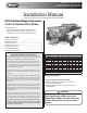


Quality since 1946
3
DC battery. This could accidentally ground the positive (+)
battery terminal, resulting in electrical shock, burns or dam-
age to the vehicle or equipment.
13. Avoid contact with battery acid. Battery acid can seri-
ously burn eyes or skin. Battery acid can also burn holes in
clothing.
14. Always disconnect the battery before removing or replac-
ing any electrical components.
15. A charging battery gives off gases that can explode if
touched by a spark or flame. Cover the top of the battery
with electrically non-conductive material to keep sparks
away from battery gases.
16. If the spreader must be operated with the spreader bat-
tery disconnected, insulate the positive (red) battery cable
and red wire from the engine alternator with electrical tape.
Installation Instructions
1. Mounting the Spreader onto the Vehicle:
A. Remove the tailgate from the vehicle.
B. Lift the spreader from the lifting loop or square knock-out
in hoppers rear cross member (toward rear of the truck).
The lifting point is placed at the approximate balance point
of the spreader. Residual material, gasoline, oil, battery, top
screen, or inverted vee assembly may affect this balance
point.
C. Elevate the spreader off the vehicle with lumber. Place
lumber under the side gussets of the spreader. This will help
with removal of excess material that accumulates under the
spreader.
D. Center the spreader on the vehicle with the ends of the
sill extensions 14" to the rear of the nearest vertical obstruc-
tion (bumper, trailer hitch, etc). It is recommended that the
Spinner/Chute Assembly be loosely attached to the hopper
to avoid any interference between the vehicle and the Spin-
ner/Chute Assembly.
E. Bolt the spreader to the vehicle frame through the lengths
of lumber using the holes located in each of the four (4) side
gussets. Use 1/2" SAE Grade 5 hardware as required by
vehicle application.
F. In addition secure the spreader to the vehicle by attach-
ing the four (4) tie-down eyes located at each corner of the
spreader to the vehicle’s factory installed anchor points us-
ing suitable tie-down devices.
• The spreader must be securely fastened to the
frame of the vehicle.
• Verify with the vehicle’s manufacturer that the
factory installed anchor points are designed for
tie-down of such load.
• Periodically check that the spreader mounting
hardware is securely tightened.
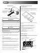
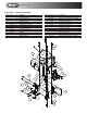
2. Mounting the Spinner/Chute Assembly
A. Attach the Spinner/Chute Assembly to the spreader using
the four (4) 3/8-16 X 3/4" hex head screws, flat washers, lock
washers, and nuts. The flat washers are to be placed over
the slots in the sill extensions. Push the chute assembly
forward towards the cab of the vehicle. Loosely attach the
hardware, but do not tighten at this time.
B. Install the roller chain between the spinner/chute sprock-
et and the gearbox sprocket. Make sure both sprockets are
in-line with one another. If the sprockets are out of align-
ment, adjust the height of the gearbox sprocket to correct
alignment. Install the roller chain master link.
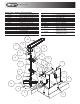
C. To adjust the roller chain tension: First pull the spinner/
chute assembly away from the rear of the vehicle to take up
slack in chain then tighten chute screws. The correct chain
tension should allow a 5/16" deflection midway between
both chain sprockets. If additional adjustment is needed,
loosen the spinner shaft bearing bolts and slide the shaft
away from the gearbox sprocket. Be sure to maintain the
vertical alignment of the spinner shaft and bearings before
tightening the hardware.
WARNING
The lifting device must be adequately rated to lift
a payload equal to or greater than the spreader
weight. See page 1 for spreader weights. Empty
spreader before lifting.
CAUTION
Do not over-tension the roller chain. This can cause
damage to the chain, bearings, and gearbox.
D. Install the chain guard using the three (3) 1/4-20 X 3/4"
hex head bolts, lock washers, and nuts.
E. Tighten all hardware to the recommended torque specifi-
cations as shown in this manual.
3. Control Box and Vehicle Wiring Harness Installation.
Note: The following instructions show how to install the
spreader so that the engine will draw power, to start the
engine, from a dedicated battery located on the spreader.