
Product Manual
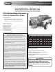


Quality since 1946
4
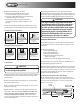
ENGAGE CLUTCH
(SPREAD)
DISENGAGE CLUTCH
(CENTER)
ENGAGE CLUTCH
(BLAST)
HOLD TO CRANK
ENGINE
RUN
ENGINE OFF
THROTTLE DOWN
THROTTLE UP
CHOKE
CIRCUIT BREAKER
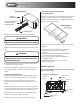
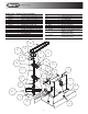
A. Layout a wiring path for the vehicle wiring harness.
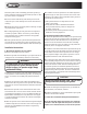
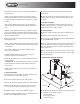
5. Installing the Inverted Vee Assembly
(Optional Equipment)
The front and rear hopper cross members have two (2) holes
in each to support the inverted vee deflector weldment.
Secure the deflector with four (4) 3/8-16 X 1" hex head cap
screws, lock washers, and nuts.
ATTACH TO
VEHICHLE GROUND
ATTACH TO 12V DC POWER
SOURCE CONTROLLED
BY VEHICLE IGNITION
TO SPREADER HARNESS
WARNING
Do not drill holes into fuel tanks, fuel lines, through
electrical wiring, etc that may be damaged by drilling.
A. Adjust the height of the inverted vee for the material be-
ing spread:
• For salt and dry sand, adjust the Deflector Weld-
ment as close to the bottom of the hopper as
possible.
• For salt/sand mix, adjust the Deflector Weldment
to the middle of the mounting holes.
• For wet sand, adjust the Deflector Weldment to
the highest position.
• Tighten all hardware according to the recom-
mended torque chart.
WARNING
Do not install control box in the vehicle’s airbag
deployment area. Refer to the vehicle’s manual for
airbag deployment area.
Cab Control Box
B. Mount the control box in a convenient location in the truck
cab.
C. Connect the green wire from the vehicle wiring harness
to a known good vehicle ground.
D. Connect the stripped end of the red wire to an accessory
wire/terminal that is controlled by the vehicle’s ignition
switch.
4. Spreader Wiring Installation
A. Attach the terminal end of the black (negative) battery
cable to the negative terminal (marked “-”) on the battery.
B. Then connect the terminal end of the red (positive)
battery cable to the positive terminal (marked “+”) on the
battery.
C. Using cable straps and 1/4" x 3/4" sheet metal screws, se-
cure the spreader wiring harness to the spreader. Predrilled
holes are provided for securing the sheet metal screws.
D. Verify that the Ignition Switch in Control Box is in the
“OFF” position prior to completing step E.
E. Connect the spreader and vehicle wiring harnesses.
Spreader Operation
Note: Before starting the engine, follow all safety precau-
tions on pages 2 and 3.
1. Cab Control Box Functions: