
Product Manual


Quality since 1946
7
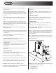
6. Maintain the correct tension on the following roller
chains:
A. Engine to Gearbox Input Sprocket.
B. Spinner Shaft to Gearbox Input Sprocket.
The correct chain tension allows 5/16" deflection midway
between respective sprockets. Oil both roller chains often,
and at the end of each season.
To loosen or tighten Chain A: loosen the four (4) 3/8-16 X
1 carriage bolts that fasten the engine mount stand to the
engine deck and slide the engine mount stand.
To loosen or tighten Chain B: First, loosen the spinner chute
fasteners and slide the spinner/chute assembly. If additional
adjustment is needed, loosen the spinner shaft bearing bolts
and slide the spinner shaft. Be sure to maintain the vertical
alignment of the spinner shaft and bearings before tighten-
ing the hardware.
7. Empty the spreader of all ice control material when not in
use to prevent a frozen feed chain.
8. Wash out the spreader when it is not in use. At the end of
the season wash out the spreader to remove all ice control
materials. Thoroughly dry all metal surfaces. Paint and oil all
bare metal surfaces and chains to protect from rust. Properly
store the spreader for the next season.
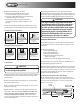
9. To minimize problems and extend the life of the electric
clutch, the following procedures are recommended:
A. At the end of the season, remove and clean the clutch.
B. After cleaning, coat both mating surfaces of the clutch
with oil or light grease.
C. Remove oil and grease prior to using the clutch again.
10. Engine Repair
A. Maintain the spreader engine according to the engine
owner’s manual. This manual is shipped with the spreader.
The engine warranty is covered by the engine’s manufac-
turer. If engine service is required, contact an authorized
service center for the engine’s manufacturer.
CAUTION
Do not over-tension either roller chain. Over-ten-
sioning can cause damage to bearings, roller chain,
sprockets, or the engine.
CAUTION
Improper installation of the throttle motor assem-
bly can result in damage to the engine choke/throt-
tle linkage.
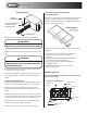
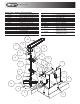
Throttle Motor Assembly Instructions
(diagram on pg. 8)
Removal Instructions:
1. Carefully observe the existing installation and mark the
position of the throttle control bracket on the engine mount
stand.
2. Disconnect the wire connections.
3. Remove the 1/4-20 fasteners that hold the throttle control
bracket to the engine mount stand. Remove the throttle mo-
tor assembly.
Installation Instructions:
1. Connect the electrical wiring. Only connect the brown
wire to brown wire and red wire to red wire.
2. Run the new throttle motor until the crank is within open-
ing of the throttle control bracket.
3. Fasten the new throttle motor to the throttle control
bracket using the existing hardware.
4. Place the throttle pin assembly on the crank of the throttle
motor using hole in the middle of
plastic block.
5. Place the assembly onto the engine mount stand by insert-
ing the throttle pin into the engine choke/throttle linkage
slider.
6. Keeping the throttle pin assembly parallel to the engine
choke/throttle linkage bolt the assembly to the engine mount
stand with the existing hardware.
7. Run throttle motor in both directions until the slider in
choke/throttle linkage stops against choke/throttle linkage
bracket. Adjust position of throttle bracket if necessary.