
Owner manual


3
TM
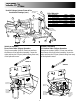
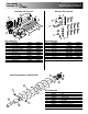
3. Spinner assembly installation: (See installation
drawings on pages 3 and 4.)
A. Attach the spinner shield (Item 2) to the spinner
frame (Item 1) using (3) 5/16-18 x 3/4 cap screws
and (3) 5/16-18 hex flange nuts.
B. Attach the spinner disk sub assembly (Item 3)
to the hydraulic motor on the spinner frame and
tighten the set screw in the disk collar.
Note: Be sure to lubricate the hydraulic motor shaft
generously with Never Seez lubricant before assem-
bling.
C. Attach the spinner frame assembly (Item 1) to
the lower tray of the spreader with the hinge rod
(Item 5) and attach (2) hairpin cotter pins.
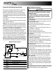
D. Weld bar (Item 7) on the outside of the truck’s
(driver’s side) main frame rail. Locate the center of
the hole in the bar (Item 7) 11-1/2" vertically below
the dump body hinge pin center.
E. Bolt the spinner lug (Item 6) and hose clamp to
the spinner frame using (1) 5/16-18 x 3/4 hex head
cap screw and (1) 5/16-18 x 1-1/2 hex head cap
screw with (2) 5/16 -18 hex nuts.
F. Attach one parallel linkage rod (Item 4) to the
spinner lug (Item 6) using (1) 1/2" flat washer and
(1) hairpin cotter pin. Attach the other parallel
linkage rod (Item 4) to the frame bar (Item 7) using
another 1/2" flat washer and another (1) hairpin
cotter pin.
G. Keeping the spinner assembly level, remove
the set screw from the clamp collar and secure the
spinner frame in place using the spinner assembly
lock.
H. Weld the (2) parallel linkage rods (Item 4) solidly
together.
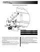
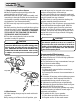
Truck Frame
Hinge Rod
Spinner
Frame
Spinner
Lug
Bar
Spreader
Dump Body
Hinge
Bar
Spinner
Frame
Spreader
Hanger Iron
Brace
Parallel Linkage, Spinner Frame & Bar
Installation Drawings