
Owner manual


5
TM
Hydraulic Installation Instructions
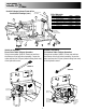
A. During assembly take precautions to keep all
hydraulic components as clean as possible.
B. Allow enough hose length to prevent kinking
and stretching of the hoses and to permit raising
the dump body. Support long hoses with wire ties
or clamps.
C. Protect hoses from wear caused by sliding and/
or vibration.
D. For proper rotation of auger and spinner motors,
hoses may be reversed.
Note: Use of a pipe joint sealant compatible with
hydraulic oil is recommended for all screw fittings.
E. Use swivel type hose ends to connect hoses to
flow valve. Damage to valve body may occur if the
fittings in flow valve are over tightened
F. To achieve a positive shutoff of the auger motor,
the inlet flow must pass through the ball valve
(pre-mounted to the spreader) & the supplied hose
must connect the ball valve to the auger’s hydraulic
motor as shown in the figures on the bottom of
page 4. (Inspection of this hose is recommended to
ensure no damage has occurred during shipping)
G. Buyers Products recommends a minimum flow
rate of 9 GPM @ 1000 rpm to operate our spreaders.
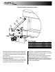
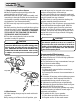
Valve
1/2" Quick Disconnects
3/4" (1)
Wire Hose
3/4" (1) Wire Hose
1/2" (1) Wire Hose
1/2" (1) Wire Hose
1/2" (1) Wire Hose
Auger Motor
CW Rotation
Ball
Valve
Spinner Motor
CCW Rotation
3/4" Quick
Disconnects
3/4" (2) Wire Hose
1-1/4" Spiral
SuctionHose
3/4" (2) Wire Hose
1/2" (1) Wire Hose
Tank
Pump
3
1
4
Hose
5
T
A
P
S
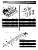
Bill of Materials
1 HV715 1 Dual Flow Regulator Valve
2 HVC1 1 Dual Flow Regulator Console
3 SMR15 1 15 Gallon Reservoir
4 3008521/ 1 Ball Valve Assembly (Stainless/Carbon)
3008523
5 3008112/ 1 Hose (Direct Drive/5:1 Gearbox)
3008113
item part no. qty. description
Hydraulic Pump Diagram
Operating Instructions
1. Pre-start up.
A. Use high grade non foaming hydraulic oil to fill
reservoir about 3/4 full.
B. Position valve on/off lever to off.
C. Move auger and spinner knobs on the valve to
the open position.
D. Engage PTO and circulate hydraulic oil for sev-
eral minutes to warm up.
E. Move valve on/off lever to on.
F. Inspect hydraulic system for leaks.
G. Check auger and spinner to see if they are work-
ing properly.
H. Refill reservoir to 3/4 full.
I. Hydraulic system should now be ready for use.
2. Initial use of spreader
A. Shut off spinner and auger knobs and position
the on/off lever to on. Engage the PTO and allow
the hydraulic system to warm up.
B. Open the cover plate and secure vertically with
locking brackets.
C. Open dump body tailgate as wide as possible
from bottom without bearing against cover plate.
Set stop chains.
D. Position spinner assembly to the far left (drivers
side), tighten clamp. Determine placement of mate-
rial at various spinner and auger speeds by spread-
ing a small amount of material (Far left position
used to spread (3) three or (4) four lane highway
from right lane).
E. Position spinner assembly to the far right (pas-
senger side), tighten clamp. Determine placement
of material at various spinner and auger speeds
by spreading a small amount of material (Far right
position used to spread (4) four lane highway from
left lane).
F. Changing auger and spinner speeds on the valve
and placing spinner at various positions from left to
right will produce various spread patterns.
CAUTION
A. Be sure everyone is standing clear.
B. Be alert for anything that may require shutting
down the system.
C. Before working in or around spreader equip-
ment, be sure all hydraulic controls are moved to
off position.