
Owner's manual


3
TM
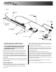
connector into the trucks cab. Secure harness to truck’s
frame.
B. Mount the Controller in a convenient location in the truck
cab. Do not mount controller directly in front of the heat
vents. Allow ample air space around controller. Protect
controller from water, dirt and dust.
C. Apply dielectric grease or similar compound to
connectors before assembly. Connect the round
connector on the wire harness to the round connector on
the controller.
D. Lay out path for the power cable in the truck’s engine
compartment. Drill hole in the firewall or use an existing
one to pass the wire harness. Passing the power cable from
inside of the cab to the battery is recommended to protect
the large high amperage connector. Do not route the power
cable close to exhaust system!
E. Connect power cable connector to controller.
F. Connect the power cable ring terminals to the truck
battery, white-positive, and black-negative.
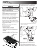
H. Secure spreader using four ratchet straps as shown in
Fig. 6. Tighten straps evenly to secure spreader in the
middle of the truck box.
12
6
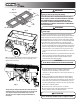
2" x 4"
2" x 6"
FIT TO BOX
FIT TO BOX
Fig. 4
Fig. 5
Verify with the vehicle’s manufacturer that the factory
installed anchor points are designed for tie-down such
load. Inspect straps and hardware after each time
spreader is loaded. Tighten straps and hardware if
necessary.
Fig. 6
2. Install Control Box & Vehicle Wiring Harness (Fig. 7).
NOTE: THIS IS A WIRE GROUND ELECTRICAL SYSTEM!
NO CONNECTIONS TO TRUCK'S FRAME OR BODY
ALLOWED! ALWAYS DISCONNECT BATTERY BEFORE
ATTEMPTING TO INSTALL ELECTRICAL COMPONENTS
ON YOUR VEHICLE.
To insure good performance of your spreader, check the
condition of truck’s electrical system. Using digital voltmeter,
check alternator and battery voltage. The voltage reading
should fall between 13.6 and 15.3 volts with engine running,
head lights and heater fan turned on. If voltage reading falls
out of this range, check and adjust your electric system.
A. Lay out a wiring path for the Vehicle Wiring Harness.
Connect the Wire Harness smaller terminal to the Chute’s
harness, large terminal to the Hopper’s harness. Drill all
necessary holes or use existing ones to pass the round
CAUTION
DO NOT MOUNT CONTROLLER IN WAY OF AIR BAG DEPLOYMENT.
DO NOT DRILL OR TAP INTO CONTROLLER! WARRANTY WILL BE VOID!
WARNING
Do not drill holes into fuel tanks, fuel lines, through electrical
wiring, etc that may be damaged by drilling.
WARNING
Use extreme caution when working around an operating
vehicle engine.
ATTENTION
Do not connect black (negative) wire to any part of vehicles
frame. Connect this terminal to battery’s negative terminal.