
Product Manual

Quality since 1946
3
1
2
3
4
6
7
8
9
10
11
12
5
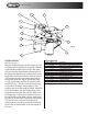
HOPPER & BAND
See Fig.1 on pg. 2
Slide the support band (4) over the hopper (2) from
the bottom until it touches the hopper lip. Slide the
hopper/band assembly over the top of the frame
tube and onto the sleeve below until the holes in
the hopper and band line up with the holes in the
frame tube. Install two 5/16-18 x 4 HH cap screws
(15) from the outside of the frame tube at the top
through the band and hopper. Include flat wash-
ers (14) on both sides and nuts (17) on the inside.
Install 5/16-18 x 3 HH cap screw (16) through the
lower hole in the frame, into the hopper, with
washers and nut on the inside of hopper. Install the
cover latch keepers onto the hopper using #10-24
socket head screws (20) and nuts (21). Make sure
the keeper (18) is facing down with the screws on
top and that the screw head is on the outside and
the nuts are on the inside. Install the cover latches
(19) onto the cover using #10-24 socket head
screws and nuts. Insert the screw thru the inside
of the cover so that the nuts are on the outside of
the cover.
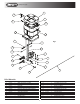
Bill of Materials
1 3005473 1 Frame, Welded, TGSUV1A w/ Sleeve
2 3005693 1 Motor, 12VDC, 1000 RPM, 1/8 HP w/ SAE Conn.
3 0202800 1 Hub, Spinner Finished
4 3003907 1 Spinner, Weldment, TGSUV1
5 - 8 Washer, Flat 1/4 SAE SST
6 - 7 Screw, CAP 1/4-20 x 3/4 SST
7 - 7 Nut, HEX 1/4-20 SST
8
-
3 Washer, 1/4 in. Spring Lock SST
9 3007502 1 Gate, Flow Adjuster, TGSUV1B
10 - 2 Screw, HHC 1/4-20 x 1-1/2 SS
11 3007502 2 Spring, Gate, TGSUV1
12 - 2 Nut, Nylon Insert 1/4-20 SST
item part no. qty. description
Fig. 2