20 WATT STEREO POWER AMPLIFIER
Safety Instructions/Consignes de sécurité/Sicherheitsvorkehrungen/Instrucciones de seguridad WARNING: To reduce the risk of fire or electric shock, do not expose this unit to rain or moisture. To reduce the hazard of electrical shock, do not remove cover or back. No user serviceable parts inside. Please refer all servicing to qualified personnel.
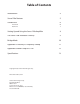
Table of Contents Introduction 4 Servo 120a Features 5 Guided Tour 6 6 7 Front Panel Rear Panel Setting Up and Using the Servo 120a Amplifier 8 The Servo 120a Protection Circuitry 9 Bridge Mode 10 Appendix A: Linearity vs. Frequency Sweep 11 Appendix B: Power Output vs. THD 12 Specifications 13 Copyright 2004, Samson Technologies Corp. Printed December, 2004 Samson Technologies Corp. 575 Underhill Blvd. P.O.
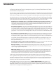
Introduction Congratulations on purchasing the Samson Servo 120a Power Amplifier! Although designed for easy operation, we suggest you first take some time to go through these pages so you can fully understand how we’ve implemented a number of unique features. The Servo 120a is a single rack-space stereo power amplifier which is optimized for use in both professional and project recording studio environments as well as for live performance.
Servo 120a Features The Samson Servo 120a Power Amplifier utilizes the latest technology in professional power amplifier design. Here are some of its main features: • Power to spare - Each channel delivers 60 watts of power into 4 ohms (or, in Bridge mode, 120 watts into 8 ohms). • Clean, crisp sound - Impressive audio specifications such as .01% THD, S/N of 105 dB, crosstalk of 75 dB, and frequency response of 3 Hz to 65 kHz guarantee ultra-clean sound quality in any live or recording environment.
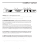
Guided Tour - Front Panel � � � � � � � � � � � � � � �� 1: Channel input level controls - These 41-position detented knobs allow you to adjust the input level of the signal arriving at the rear-panel input jacks (see #4 and #5 on the following page). At their fully counterclockwise position, the signal is attenuated by 70 dB (essentially completely off ). At their fully clockwise position, the signal is at unity gain (that is, no attenuation).
Guided Tour - Rear Panel � � � � � � � � � 1: AC Input - Connect the supplied standard 3-pin “IEC” plug here. 2: Fuse Holder - Insert a 2.5 amp, SLO-BLO 125 volt fuse here for 115 volt operation, or a 1.5 amp, SLO-BLO 250 volt fuse for 230 volt operation. WARNING: Fuses should only be replaced with the power cord disconnected. 3: 5-way Binding Post Output Connectors - Use these to connect each channel of the Servo 120a to loudspeakers.
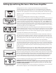
Setting Up and Using the Servo 120a Power Amplifier Setting up your Servo 120a is a simple procedure which takes only a few minutes: 1. Remove all packing materials (save them in case of need for future service) and decide where the amplifier is to be physically placed—it can be used free-standing or mounted in a standard 19" rack, requiring only one rack space.
The Servo 120a Protection Circuitry As noted in the “Guided Tour” section of this manual, the Servo 120a's front panel Protection LED indicates the activity of the relay speaker connection circuitry. When the Protection LED is lit, this circuitry is inactive, and all connected speakers are muted (provided with 0 volts DC), thus protecting them and preventing any audible “thump” from occurring.
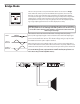
Bridge Mode The Servo 120a provides a rear-panel switch that allows it to be used in a Bridge mode. When this switch is placed in the “RIGHT” (Stereo) position, the Servo 120a functions as a true stereo amplifier, where both of the two independent amplifier channels (left and right) can receive different input signals and produce independent output signals.
Appendix A: Linearity vs. Frequency Sweep AUDIO PRECISION Servo 120a LEVEL (dBr) vs FREQ (Hz) 0dB ref 5.0000 4.0000 Ap 3.0000 2.0000 1.0000 0.0 -1.000 -2.000 -3.000 -4.000 -5.000 10 100 1k Linearity (0 dB Ref) vs.
Appendix B: Power Output vs. THD AUDIO PRECISION Servo 120a THD +N (%) & LEVEL (W) vs FREQ (Hz) Watts THD 1.000 80.000 Ap .9000 73.000 61.000 .8000 56.000 .7000 48.000 .6000 40.000 .5000 32.000 .4000 21.000 .3000 15.000 .2000 8.000 .1000 200.0u 20 100 1k 10k Power output (60 W) vs. Total Harmonic Distortion 12 50k 0.
Specifications Rated Output Power, per channel (@ 1 kHz) Stereo mode 4 ohm, .<0.05% THD+N 4 ohm, 1% THD+N 8 ohm, <0.05% THD+N 8 ohm, 1% THD+N Bridge mode 8 ohm, .<0.05% THD+N 8 ohm, 1% THD+N 60 W 80 W 50 W 55 W 120 W 150 W Typical Distortion, per channel THD+N (80 kHz LPF @ 1 kHz, rated output power) IMD (SMPTE 4:1, 60 Hz & 7 kHz @ rated output power) .01% .03% Signal To Noise Ratio (22 Hz - 22 kHz bandwidth @ dB below rated output power) 10 Hz - 20 kHz +0, -0.5 dB 3 Hz - 65 kHz, +0, -3.
Notes 14
Samson Technologies Corp. 575 Underhill Blvd. P.O. Box 9031 Syosset, NY 11791-9031 Phone: 1-800-3-SAMSON (1-800-372-6766) Fax: 516-364-3888 www.samsontech.