WIRELESS WIRELESS WIRELESS BELTPACK BELTPACK BELTPACK SYSTEM SYSTEM SYSTEM
7!2.).' 4/ 02%6%.4 &)2% /2 3(/#+ (!:!2$ $/ ./4 53% 4()3 0,5' 7)4( !. %84%./. #/2$ 2%#%04!#,% /2 /4(%2 /54,%4 5.,%33 4(% ",!$%3 #!. "% &5,,9 ).3%24%$ 4/ 02%3%.4 ",!$% %80/352% 4/ 02%6%.4 &)2% /2 3(/#+ (!:!2$ $/ ./4 %80/3% 4()3 !00,)!.#% 4/ 2!). /2 -/)3452% 4/ 026%.4 %,%#42)#!, 3(/#+ -!4#( 7)$% ",!$% 0,5' 4/ 7)$% 3,/4 &5,,9 ).3%24 #!54)/. 2)3+ /& %,%#42)# 3(/#+ $/ ./4 /0%.
ATTENTION: Pour éviter tout risque d’électrocution ou d’incendie, ne pas exposer cet appareil à la pluie ou à l’humidité. Pour éviter tout risque d’électrocution, ne pas ôter le couvercle ou le dos du boîtier. Cet appareil ne contient aucune pièce remplaçable par l'utilisateur. Confiez toutes les réparations à un personnel qualifié. Le signe avec un éclair dans un triangle prévient l’utilisateur de la présence d’une tension dangereuse et non isolée dans l’appareil.
PRECAUCION: Para reducir el riesgo de incendios o descargas, no permita que este aparato quede expuesto a la lluvia o la humedad. Para reducir el riesgo de descarga eléctrica, nunca quite la tapa ni el chasis. Dentro del aparato no hay piezas susceptibles de ser reparadas por el usuario. Dirija cualquier reparación al servicio técnico oficial.
Copyright 2008-2009, Samson Technologies Corp. Printed January, 2009 v1.1 Samson Technologies Corp. 45 Gilpin Avenue Hauppauge, New York 11788-8816 Phone: 1-800-3-SAMSON (1-800-372-6766) Fax: 631-784-2201 www.samsontech.
Table of Contents Introduction. . . . . . . . . . . . . . . . . . . . . . . . . . . . . . . . . . . . . . . . . . . . . . . . . . . . . 1 QuickStart. . . . . . . . . . . . . . . . . . . . . . . . . . . . . . . . . . . . . . . . . . . . . . . . . . . . . . . 2 QuickStart. . . . . . . . . . . . . . . . . . . . . . . . . . . . . . . . . . . . . . . . . . . . . . . . . . . . . . . 3 Guided Tour - AR300 Receiver / Front Panel . . . . . . . . . . . . . . . . . . . . .
Introduction Welcome to Samson AirLine Synth—the next generation of wireless systems! Wireless microphone and instrument systems were originally developed to eliminate cables, providing unparalleled freedom of movement. AirLine Synth takes this concept to a new level with transmitters so small, lightweight and aerodynamic, they are nearly invisible, providing a completely “hassle-free” user experience.
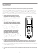
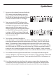
QuickStart If you’ve had some prior experience using wireless systems, these QuickStart instructions will get you up and running with your AirLine UHF wireless system in a matter of minutes! Detailed instructions for setting up and using your AirLine Synth system can be found on page 15 of this manual, and the “Guided Tour” sections on pages 10 - 14 provide full descriptions of all AirLine component controls and displays. 1.
QuickStart 7. Now to set the channel, press and hold the EDIT control until the display shows the group number with three asterisks. Next, the AR300 will display the selected Channel number and then the IR SET will begin. 8. Once you see the IR SET flashing in the LCD, hold the AL300 transmitter, with the IR window facing the front of the AR300, approximately 6 inches away from the receiver and turn the AL300 power switch on.
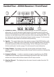
Guided Tour - AR300 Receiver / Front Panel 1. Antennas (A and B) - The antenna mountings allow full rotation for optimum placement. In normal operation, both Antenna A (the antenna on the left) and Antenna B (the antenna on the right) should be placed in a vertical position. Both antennas can be folded inward for convenience when transporting the AR300. See the “Setting Up and Using the AirLine Synth System” section on page 15 in this manual for information about antenna installation and positioning.
Guided Tour - AR300 Receiver / Front Panel 6: EDIT Control – This rotary encoder control knob/switch is used to control and set several menu functions and parameters displayed in the LCD display and it is also used to preform the automatic Channel Scan. 7: Power Switch - Use this to turn the AR300 power on and off. When the receiver is on, the LCD backlight is lit. 8: IR Transmitter – During “IR SET” an Infrared light is used to set the transmitter channel.
Guided Tour - AR300 Receiver / Rear Panel A A B C E D A: Antenna socket - D hole knockout for mounting the antennas to the rear panel using the optional rear antenna kit. B: DC input - Connect the supplied power adapter here, using the strain relief as shown in the illustration below. WARNING: Do not substitute any other kind of power adapter; doing so can cause severe damage to the AR300 and will void your warranty.
Guided Tour - AL300 Transmitter 1: LCD Display – This three digit Liquid Crystal Display indicates the Absolute Channel number that the transmitter is set to. 2: 15 dB Pad - Move this switch in the direction of the arrow to reduce the output of the AL300 by 15 dB when your microphone is putting out too hot a signal. See the “Setting Up and Using the AirLine Synth system” section on page 12 in this manual.
Guided Tour - AL300 Transmitter 6: A ntenna - This permanently attached flexible antenna should be fully extended during normal operations. See the “Setting Up and Using the AirLine Synth system” section on page 2 in this manual for more information about antenna positioning. 6 7 7: IR Lens - This acrylic window is used to capture the infrared signal sent from the AR300 during the IR SET to channelize the AL300.
Setting Up and Using Your AirLine Synth sysThe basic procedure for setting up and using your AirLine Synth system takes only a few minutes: 1. Remove all packing materials (save them in case of need for future service) and check to make sure that the supplied power adapter is the correct voltage for your country. If not, contact your distributor or, if purchased in the United States, Samson Technical Support at 1-800-372-6766. 2. Physically place the AR300 receiver next to your mixer.
Setting Up and Using Your AirLine Synth system 6. Make the physical cable connection between the AR300 output jack and an audio input of your amplifier or mixer. Leave your amplifier or mixer off at this time. 7. Turn the Level knob on the AR300 completely counterclockwise, then slide its Power switch in the direction of the arrow to turn it on. The LCD display light will illuminate. 8. Now to set the channel, press and hold the EDIT control until the display reads CH SCAN.
Setting Up and Using Your AirLine Synth system 12. Temporarily turn down the level of your mixer or amplifier and turn off the power to your transmitter, leaving the AR300 receiver on. Then restore the previously set level of your mixer or amplifier. With the transmitter off, the receiver output should be totally silent; if it is, skip ahead to the next step. If it isn’t (that is, if you hear some noise), you may need to adjust the AR300 Squelch control.
AR300/AL300 Operation Setting a Group and Channel Manually The AR300 receiver contains over 300 selectable channels that are organized into a series of Groups. Each Group contains channels that are compatible for simultaneous use. When using multiple systems, you’ll want to assign each system to the same Group in order to maximize the number of compatible channels. Each of the Groups has six to ten channels.
AR300/AL300 Operation Operating In FREE Mode You can tune in an exact frequency using the AR300’s FREE mode. Once you are in FREE mode you can change the frequency by 25 kHz steps. For most situations, it’s better to use the GROUP Channel plan but if your application requires an exact frequency, follow these steps to operate in FREE mode. 1. Press the EDIT controller three times until the display’s FREE icon turns on and Frequency number flashes. 2.
Specifications SYSTEM SPECIFICATIONS Channels 319 channels 25kHz Step Operating Frequency N Band 639.025MHz-6476.975MHz (USA) U Band 798.025MHz-806MHz (Export) Frequency Type F3E Modulation Type FM Noise Reduction Type Compander Distance 100 meters line of sight Audio Frequency Response 50Hz - 15KHz (+/- 3dB) Dynamic Range >100dB (IHF-A) AR300 RECEIVER Oscillation System VCO Type of Reception Double superheterodyne / True Diversity Intermediate Frequency 10.
Specifications TRANSMITTER (AL300) Oscillation Type Crystal-controlled PLL frequency systhesized Modulation Type FM Antenna 1/4 Wave Length Wire Type Input Impedance 290k ohms(ATT:0dB), 330k ohms(ATT:-15dB) Maximum Input Level -2dBv(ATT:0dB), +15dBv(ATT:-15dB) Switches/Controls POWER switch, MUTE switch, ATT switch, GAIN control Display CHANNEL (LCD), BATT (LED) Interface Infrared Phantom 3V (0.9mA at short) Impedance 2.
FCC Rules and Regulations Samson wireless systems are type accepted under FCC rules parts 90, 74 and 15. Licensing of Samson equipment is the user’s responsibility and licensability depends on the user’s classification, application and frequency selected. This device complies with RSS-210 of Industry & Science Canada.
Samson Technologies Corp. 45 Gilpin Avenue Hauppauge, New York 11788-8816 Phone: 1-800-3-SAMSON (1-800-372-6766) Fax: 631-784-2201 www.samsontech.