
Operation Manual


Auro D208/D210
8
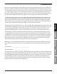
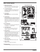
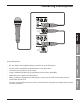
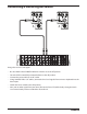
1. XLR Input Connector
This female XLR connector accepts either a
balanced microphone or line level signal.
2. 1/4” Input Connector
Use this 1/4” input for connecting balanced
microphone or balanced and unbalanced
line level inputs.
3. Line Output
Male XLR connector used to link multiple
Auro cabinets.
4. Level Control
This control adjusts the overall signal level at
the input of the power ampliers. For attenu-
ating a line level signal, turn the control from
fully counter-clockwise until 12 o’clock. For a
mic level signal turn the Level control past 12
o’clock.
5. Bass EQ Control
This controls the low band of the loudspeak-
er equalizer, +/- 15 dB at 80 Hz.
6. Treble EQ Control
This controls the high band of the loud-
speaker equalizer, +/- 15 dB at 12 kHz.
7. Peak Indicator
This RED LED lights when the amp is near the
clipping point. If the Peak indicator lights
frequently, turn down the Level control on
the Auro loudspeaker or turn down the
signal at the source, until the indicator does
not light anymore, or lights occasionally with
signal peaks.
8. Power Indicator
This LED lights GREEN when amp is active.
9. Power Switch
Switches on the Auro’s main power.
10. AC Power Inlet
Connect the supplied standard IEC AC power cable here.
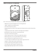
Rear Panel Layout
9
10
2 1
3
4
5
6
7
8