MXP144/MXP144FX STEREO MIXERS OWNER’S MANUAL
Important Safety Information EMC Notice • MXP144 and MXP144FX can be used in following electromagnetic environment: residential, commercial and light industrial, urban outdoors. • For MXP144 and MXP144FX, the peak inrush current is 4.90 A FCC Notice This device complies with part 15 of the FCC Rules.
Important Safety Information ATTENTION RISQUE DE CHOC ÉLECTRONIQUE NE PAS OUVRIR WARNING: TO REDUCE THE RISK OF ELECTRIC SHOCK, DO NOT REMOVE COVER (OR BACK) AS THERE ARE NO USER-SERVICEABLE PARTS INSIDE. REFER SERVICING TO QUALIFIED SERVICE PERSONNEL.
Important Safety Information 1. Read these instructions. 2. Keep these instructions. 3. Heed all warnings. 4. Follow all instructions. 5. Do not use this apparatus near water. 6. Clean only with dry cloth. 7. Do not block any ventilation openings. Install in accordance with the manufacturer’s instructions. 8. Do not install near any heat sources such as radiators, heat registers, stoves, or other apparatus (including amplifiers) that produce heat. 9.
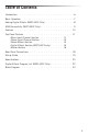
Table of Contents Introduction . . . . . . . . . . . . . . . . . . . . . . . . . . . . 6 Basic Operation . . . . . . . . . . . . . . . . . . . . . . . . . . 7 Adding Digital Effects (MXP144FX Only) . . . . . . . . . . . . . . 8 USB Connectivity (MXP144FX Only) . . . . . . . . . . . . . . . . 9 Features . . . . . . . . . . . . . . . . . . . . . . . . . . . . . 10 Top Panel Controls . . . . .
Introduction Congratulations on your purchase of the Samson MixPad MXP144 or MXP144FX mixer! The MXP144 and MXP144FX are 12-channel mixers, with four mic/line channels with low-noise, microphone preamps, two stereo channels with XLR mic inputs and ¼” line input channels, and two stereo line input channels with RCA and ¼” inputs. The input channels feature a 3-band equalizer and 60mm faders. The microphone inputs have gain controls, and high-pass filters.
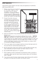
Basic Operation The following section explains the basic setup and operation of the MixPad MXP144 and MXP144FX. 1. Before connecting any microphones or instruments, make sure that the power of all your systems components including the MixPad mixer is turned off. Make sure that the MAIN MIX and MIX 2/PHONES controls are turned all the way down. 2. Connect the cables from your microphones and instruments to the mixer. Microphones should be connected to the XLR inputs of channels 1-4.
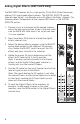
Adding Digital Effects (MXP144FX Only) The MXP144FX features built-in, high quality, 24-bit Multi Effect Processors, offering 100 studio grade effects presets. The DIGITAL EFFECTS section features clean Delays, lush Reverbs and multi-effects like Delay + Reverb. The following details the operation of the internal DSP effects in the DIGITAL EFFECTS section. 1.
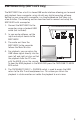
USB Connectivity (MXP144FX Only) The MXP144FX has a built-in stereo USB audio interface allowing you to record and playback from a computer using virtually any digital recording software. Setting up your mixer with a computer is a simple procedure that takes just a few minutes. The following section describes how to connect and setup the MXP144FX with a computer. 1. Connect the MXP144FX to the computer using a standard USB cable (not included). 2.
Features The Samson MixPad mixers are comprehensive, all-in-one solution for live sound, recording, fixed installation and post production applications.
Top Panel Controls Mono Input Channel Section The following section details four mono input channels. 1. 2. MIC Inputs - Use these balanced XLR inputs to connect low Impedance microphones and low level signals from direct boxes. The MIC inputs feature +48V phantom power, allowing you to use condenser microphones.
7 Top Panel Controls 8. 9. MON Auxiliary Control - Controls the amount of that channel’s signal that is sent to the MON Output. The signal feeding MON is sent before, or pre, the channel fader, so the channel fader has no effect on the MON level. The MON is usually used to create a separate mix for a floor monitor system. 8 9 10 FX Auxiliary Control - FX Auxiliary Control - The channel’s FX knob controls the amount of signal that is sent to the effects bus.
Top Panel Controls Stereo Input Channel Section The following section details four stereo input channels. 14. MIC Inputs (CH5/6 & CH7/8) - Use these balanced XLR inputs to connect low Impedance microphones and low level signals from direct boxes. The MIC inputs feature +48V phantom power, allowing you to use condenser microphones. XLR Connector pin-out - Pin 1: Ground, Pin 2: Hot (+), Pin 3: Cold (-) 14 15 15. Stereo ¼” Input Jacks - Use the ¼” jacks for connecting stereo line level sources.
18 Top Panel Controls 20. 21. BAL Control - This control is used to place, or position, the stereo signal into the main left and right stereo mix field. You can create a stereo image by panning some input signals to the left and others to the right. PEAK Indicator - This LED indicator will flash RED when the channel input signal peaks. To reduce distortion, turn the LEVEL control counterclockwise or lower the volume of the input device until the clip indicator does not light during normal use. 22.
Top Panel Controls Digital Effects Section (MXP144FX only) The following section describes the features control of the on-board 24-bit digital Multi-effects section. 28. PROGRAM Effects Display - The mixer’s multi-effects processors feature a dual digit, seven-segment numerical display for showing the effects PROGRAM number from 00 - 99. 29. SELECT Control Knob - The SELECT control knob is a continuously variable encoder to call up one of the 100 built-in digital effects presets.
Top Panel Controls Master Section This following section details the master section of the mixer. 34. 35. TAPE IN (RCA jacks) - Stereo line level input, on RCA connectors, for connecting the output of devices such as MP3, CD, computer sound-card, or any other line level device. TAPE OUT (RCA jacks) - The signal present at this connector is the MAIN bus signal before it has passed through the MASTER level control and graphic equalizer. The nominal output level is -10dBV and the impedance is 100 Ohms.
Top Panel Controls 42. POWER Indicator - The POWER LED lights up to indicate that the main POWER switch (located on the rear panel) is on. 43. Output Level Meter - The output level meter allows you to monitor the level of the signal, which is being sent to the MAIN MIX jacks. NOTE: To avoid distortion, adjust the MAIN MIX level control so that the 0 indicator LED lights occasionally. 44.
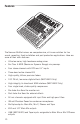
Rear Panel Connections This following section details the rear panel connections. A B C A. AC Inlet - Connect the supplied power cable here. B. POWER - Switches on the MXP144 and MXP144FX main power. C. USB Port (MXP144FX Only) - Connect the MixPad mixer to a computer using standard USB cable here.
Wiring Guide There are several ways to interface the MXP mixer to support a variety of applications. Follow the cable diagrams below for connecting your mixer.
Specifications Frequency Response (Trim @ Min, unity gain ± 3 dB) Mic to Main 20Hz~30KHz Line to Main 20Hz~30KHz Aux Return to Main 20Hz~30KHz Line to Aux Send 20Hz~30KHz T.H.D. (Trim @ Min, +4dBu output, unity gain, 1 kHz w/30 kHz LPF) Mic/Line to Main (Mono Ch) <0.03% Line to Main (Stereo Ch) <0.03% Line to Aux Send <0.
Specifications Phantom Power 48V±3V Power Requirement AC100~240V 50~60Hz Fuse T1.6A AL250V Power Consumption <48W Dimensions (W x D x H) 15.3” x 14.5” x 3.9” 391 mm x 370 mm x 100 mm Weight 8.3lb / 3.8kg USB Bus Power USB2.0 +5V DC 0.
Digital Effects Program List (MXP144FX Only) 22 Number Effect Parameter 00-09 Echo Delay Time: 145~205ms 10-19 Echo + Verb Delay Time: 208~650ms Decay Time: 1.7~2.1s 20-29 Tremolo Rate: 0.6~5Hz 30-39 Plate Decay Time: 0.9~3.6s 40-49 Chorus Rate: 0.92~1.72Hz 50-59 Vocal Reverb Decay Time: 0.8~0.9s Pre-Delay: 0~45ms 60-69 Rotary Modulation Depth: 20~80% 70-79 Small Room Decay Time: 0.7~2.1s Pre-Delay: 20~45ms 80-89 Flanger + Verb Decay Time: 1.5~2.9s Rate: 0.8~2.
2TK TAPE IN STEREO RETURN STEREO IN 5e 4d 2b 1a 0dB 0dB 5e 3c 4d 2b 1a 5e 3c 4d 2b 1a 5e 3c 4d 2b 1a 5e 3c 4d 2b 1a 5e 0dB -10dBV RIGHT LEFT RIGHT LEFT(MONO) RIGHT LEFT(MONO) RIGHT LEFT RIGHT 4d 2b 1a +20~-20dB3c 5e 3c 4d 2b 1a -5dB~-45dB LEFT(MONO) MIC IN 2 3 1 PHANTOM POWER +48V 5e 3c 4d 2b 1a +20~-20dB INSETR LINE IN CHANNELS (9/10,11/12) STEREO IN CHANNELS (5/6,7/8) 2 3 1 -5dB~-45dBu 3c MIC IN GAIN + + + + + + COMP.
Samson Technologies Corp. 45 Gilpin Avenue Hauppauge, New York 11788-8816 Phone: 1-800-3-SAMSON (1-800-372-6766) Fax: 631-784-2201 www.samsontech.