
User's Manual


7
Concert 99 Wireless System
ENGLISHFRANÇAISDEUTSCHEESPAÑOLITALIANO
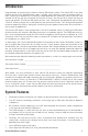
1 12 3 4
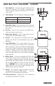
Using the strain relief: Gather up a loop of wire and pass it
through the strain relief, then pass the adapter plug through
the loop in order to create a knot.
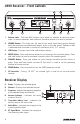
CR99 Receiver - Rear Callouts
1. Antenna Jacks - The rear BNC antenna jacks allow full rotation for optimum placement.
In normal operation, both antennas should be placed in a vertical position.
2. DC Input - Connect the supplied power adapter here, using the strain relief as shown
in the illustration below. WARNING: Do not substitute any other kind of power
adapter. Doing so can cause severe damage to the CR99 and will void your warranty.
3. BALANCED OUTPUT - Use this electronically balanced low impedance (600 Ohm)
XLR jack when connecting the CR99 to professional (+4dBu) audio equipment. Pin
wiring is as follows: Pin 1 ground, Pin 2 high (hot), and Pin 3 low (cold).
4. UNBALANCED OUTPUT - Use this unbalanced high impedance (5K Ohm) 1/4" jack
when connecting the CR99 to consumer (-10dBV) audio equipment. Wiring is as
follows: tip hot, sleeve ground.