
Datasheet


Chip Resistor
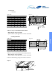
● MOUNTING
Our products have Ag electrodes protected by double layer.
▶ 1st Ni Coating
- This prevents Ag electrode from leaching and enhance the bonding with Sn
▶ 2nd Sn Coating
- This is made of Sn 100% with melting point 232℃ to prevent it from melting when solder
cream melts, and to enhance the bonding.
- Commercial solder creams are made of Sn-3.0Ag-0.5Cu with melting point 217℃.
● CLEANING
● CAUTION FOR CHIP RESISTOR SEPERATION FROM PCB
● OTHERS
Proper nozzle height must be given attention so as not to give excessive pressure on the
chip during mounting on the PCB.
(Excessive pressure may cause exterior damage, change in resistance, circuit open, etc.)
If rosin flux is used, cleaning usually is unnecessary. When strongly activated flux is used, chlorine in the
flux may dissolve into some types of cleaning fluids, thereby affecting the chip capacitors.
This means that the cleaning fluid must be carefully selected, and should always be new.
Chip resistor installation on PCB is similar phenomenon as chocolate chip on top of cake.
PCB has enough flexibility on outer force but Chip resistor can be defected without any bending.
(By chip resistor use of Ceramic, solder, metal)
Therefore, when separate from Chip resistor on PCB, be ware of any crack of chip
▶ Manual work
Manual soldering can pose a great risk of creating thermal cracks in chip resistors.
The hot soldering iron tip comes into direct contact with the end terminations, an operator's
carelessness may cause the tip of the soldering iron to come into direct contact with the
ceramic body of the resistor.
Therefore the soldering iron must be handled carefully, and close attention must be paid
to the selection of the soldering iron tip and to temperature control of the tip.
▶ Do not use more than rated voltage.(check the contents on the file)
● SOLDERING