February 2012
We declare that all our tantalum capacitors are produced in accordance with EU ROHS and REACH Directive. 1. RoHS Compliance The following restricted materials are not used in packaging materials as well as products in compliance with the law and restriction. - Cd, Pb, Hg, Cr+6, PBB, PBDE 2. No use of materials breaking Ozone layer The following ODS materials are not used in our fabrication process.
CONTENTS Precautions in using Tantalum Capacitors 4 Precautions in using Tantalum Capacitors 4 Characteristics Explanation 8 4 Characteristics Explanation Manganese Dioxide Type Conductive Polymer Type Marking & Taping Specification SCN Series -Standard series 14 SCN Series SCS Series -Extended series 17 SCS Series SCS P Series -2012 size miniaturized 21 SCS P Series SCM Series -1608 size ultra miniaturized 23 SCM Series SCF Series -Face-Down type 25 SCF Series SCE Series -Low-ESR 2
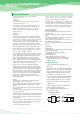
Precautions in using Tantalum Capacitors Operational Attentions The operational attentions to the use of the tantalum capacitors are as follows: •Electrical •Environmental •Conditions for mounting on equipment and circuit boards •Mechanical vibration, shock If the tantalum capacitors are used without satisfying any one of these conditions, the probability of short-circuiting, current leakage or other problems to occur increases.
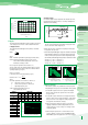
80% 60% Recommended range 20% 0 -55 -40 -20 20 40 60 80 100 125 0 Rating Voltage Operating Voltage 4 Characteristics Explanation Working Voltage Operating temperature(℃) Fig. 3 Time (sec) Fig. 5 2. Ripple The maximum permissible ripple voltage and current are related to the ratings case size. Please consult us detail informations. 2.
4.1 General The failure rate of the tantalum capacitor varies with the derating ratio, ambient temperature, circuit resistance, circuit application, etc. Therefore, when proper selections are made so as to afford additional margins, higher reliabilities can be derived from the tantalum capacitors. Some examples of actual failure rates are presented below for your reference. 4.
(2) Reflow soldering see figures 5. Mounting Precautions 5.1 Limit Pressure on Capacitor Installation with Mounter A capacitor that has been damaged should be discarded to avoid later problems resulting from mechanical stress. Pressure must not exceed 4.9 N with a tool end diameter of 1.5 mm when applied to the capacitors using an absorber, centering tweezers, or the like.
4 Characteristics Explanation 1. Capacitance 2. Voltage 1-1. Rated Capacitance(CR) This is the nominal rated capacitance. capacitance is measured at 120㎐, 1.0V RMS, DC Bias 1.0V~2.0V 1-2. Capacitance tolerance This is the permissible variation of the actual value of the capacitance from the rated value. Available in standard EIA nominal values with ±20% & ±10% tolerance. 1-3. Temperature dependence of capacitance. The capacitance of a tantalum capacitance varies with temperature. TYPICAL CAPACITANCE VS.
3. Dissipation Factor (D.F.) continuous application of reverse voltage without normal polarization will result in a degration of leakage current. The peak reverse polarity voltage applied to the capacitor must not exceed: at +20℃, 10% of rated voltage at +85℃, 5% of rated voltage or 1V,whichever is greater. 3.Dissipation factor (D.F.) Refer to part number tables for maximum DF limits. Dissipation factor is measured at 120 Hz, 1.0Volt RMS and 1.0~2.0 volts DC at +25℃.
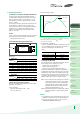
4. D. C. Leakage Current S2 RS A S1 + Cx V + - 1.0 Multiplier of Leakage Current The leakage current is dependent on the voltage applied, the elapsed time since the voltage was applied the component temp. it is measured at +25℃ with the rated voltage applied. the rated d.c voltage shall be applied to terminals across the test capacitor Cx. by the method as shown below. 0 0.01 0.
5. Impedance(Z) & ESR DF Multiplier TYPICAL DF VS TEMPERATURE 1.8 1.7 1.6 1.5 1.4 1.3 1.2 1.1 1 0.9 0.8 -55 XL=2πf L where: f =frequency, Hertz L=inductance, Henries Z Precautions in using Tantalum Capacitors δ XC -5 45 Temperature(Celcius) 4 Characteristics Explanation Ø 95 ESR 4. Impedauce(Z), and Equivalent Series Resistance(ESR) 4-1 Impedance(Z) The impedance is measured at 25℃ and 100KHZ. this is the ratio of voltage to current at a specified frequency.
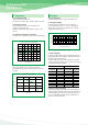
Manganese Dioxide Type Feature EMC Lead Frame Tantalum wire Tantalum Power Positive C / Ag MnO2 Ta2O5 Dielectric Negative Configuration And Dimension Normal type W1 L Z Face - down type Z L W2 H W1 Z Z H W2 Unit : mm Case Code EIA Code L W1 W2 H U I 1005 1005 K 1608 -9 0.6±0.1 0.60 max 0.55 max 0.85+0.15 - 0.1 0.8±0.1 0.25±0.1 0.25±0.1 1608 -10 K 1608 -9 0.6±0.1 0.90max 0.4±0.1 R P P S A T B C D 2012L 2012 2012 3216L 3216 3528L 3528 6032 7343 0.5±0.2 0.5±0.2 0.85+0.
Manganese Dioxide Type Series System Diagram SCF Face down type 1005size Uitra miniaturized 1608, 2012size High Capacitance Face down terminal type Precautions in using Tantalum Capacitors 4 Characteristics Explanation SCN Series SCM 1608size Miniaturized 1608 Miniaturized SCS Series SCS-P Series SCM Series SCL SCS SCE Low Profile Extended series Low ESR Low Profile 2102~7343size Low ESR 3216~7343size SCN SCF Series SCE Series SCL Series Standard series PCS Series 3216~7343size Low C
SCN (Standard Tantalum Chip Capacitors) Feature The product is a standard type that has been most widely used among tantalum chip capacitors. ·Molded case available in four case codes. ·Compatible with automatic pick and place equipment. ·Meets or exceeds EIA standard 535BAAC. ·Environment-Friendly(Pb-free) tantalum capacitor. Specifications Capacitance Range Tolerance Dissipation Factor (Tan δ) C≤1.0㎌ 1.5㎌≤C≤6.8㎌ 10㎌≤C≤68㎌ C≥100㎌ 0.15㎌ to 68㎌ ±20%(M), ±10%(K) D.F≤4.0% D.F≤6.0% D.F≤8.0% D.F≤10.
Ratings & Part Number Reference Part Number Case Size Capacitance (μF) DC Leakage (μA)@+25℃Max. DF (%)@+25℃ 120Hz Max. ESR (Ω)@+25℃ 100KHz Max. 6 6 6 6 6 6 6 6 10.0 8.0 3.5 2.5 1.8 1.8 1.0 0.8 4 volt Rating@+85℃(2.5 volt Rating@+125℃) TCSCN0G225 AAR TCSCN0G335*AAR TCSCN0G106*BAR TCSCN0G156*CAR TCSCN0G226*CAR TCSCN0G336*CAR TCSCN0G476*DAR TCSCN0G686*DAR * A A B C C C D D 2.2 3.3 10 15 22 33 47 68 0.5 0.5 0.5 0.6 0.9 1.3 1.9 2.7 A A B C C C D D 1.5 2.2 6.8 10 15 22 33 47 0.5 0.5 0.5 0.6 0.9 1.
Part Number Case Size Capacitance (μF) DC Leakage (μA)@+25℃Max. DF (%)@+25℃ 120Hz Max. ESR (Ω)@+25℃ 100KHz Max. 25 volt Rating@+85℃(16 volt Rating@+125℃) TCSCN1E334*AAR A 0.33 0.5 4 15.0 TCSCN1E474*AAR A 0.47 0.5 4 14.0 TCSCN1E155 BAR B 1.5 0.5 6 5.0 TCSCN1E335*CAR C 3.3 0.8 6 2.5 2.4 * TCSCN1E475 CAR C 4.7 1.2 6 TCSCN1E685 DAR D 6.8 1.7 6 1.4 TCSCN1E106*DAR D 10 2.5 6 1.0 TCSCN1V154*AAR A 0.15 0.5 4 19.0 TCSCN1V224 AAR A 0.22 0.5 4 18.
SCS (Miniaturized Tantalum Chip Capacitors) Feature Miniaturized tantalum chip capacitors with extened capacitance. (Reduced size 1/2 to 1/3 in comparison with SCN.) ·Molded case available in four case codes. ·New low profile size. ·Compatible with automatic pick and place equipment. ·Meets or exceeds EIA standard 535BAAC. ·Environment-Friendly(Pb-free) tantalum capacitor.
Ratings & Part Number Reference Part Number Case Size TCSCS0E227 BAR B TCSCS0G475*AAR TCSCS0G685*AAR TCSCS0G106*AAR TCSCS0G156*AAR TCSCS0G156*BAR TCSCS0G226*AAR TCSCS0G226*BAR TCSCS0G336*AAR TCSCS0G336*BAR TCSCS0G476*AAR TCSCS0G476*BAR TCSCS0G476*CAR TCSCS0G686*BAR TCSCS0G686*CAR TCSCS0G107*AAR TCSCS0G107*BAR TCSCS0G107*CAR TCSCS0G107*DAR TCSCS0G157*CAR TCSCS0G157*DAR TCSCS0G227MBAR TCSCS0G227*CAR TCSCS0G227*DAR TCSCS0G337*DAR TCSCS0G477*DAR A A A A B A B A B A B C B C A B C D C D B C D D D TCSCS0J335
Part Number Case Size Capacitance (μF) DC Leakage (μA)@+25℃Max. DF (%)@+25℃ 120Hz Max. ESR (Ω)@+25℃ 100KHz Max. 8 8 8 8 8 8 8 8 8 8 8 8 12 8 8 20 8 8 8 8 8 8 8 8 8 8.0 6.0 6.0 6.0 3.5 2.0 3.5 4.0 3.5 2.0 3.0 1.8 2.0 1.8 1.6 3.0 1.6 1.2 0.8 0.9 0.8 1.2 0.7 0.8 0.4 8 8 8 8 8 8 8 8 8 8 8 8 8 8 8 8 8 8 8 8 8 8.0 6.0 6.0 4.0 3.5 3.5 3.5 3.0 3.5 3.0 1.8 2.3 1.6 1.4 1.5 0.8 1.4 0.8 1.4 0.8 0.7 10 volt Rating@+85℃(6.
Part Number Case Size Capacitance (μF) DC Leakage (μA)@+25℃Max. DF (%)@+25℃ 120Hz Max. ESR (Ω)@+25℃ 100KHz Max. 6 8 8 8 8 8 8 8 8 8 8 6 8 8 8 8 8 8 8 10.0 8.0 7.0 4.0 3.5 3.5 3.5 3.5 3.0 1.8 1.7 1.8 1.6 0.8 1.2 0.8 0.7 0.7 0.9 6 6 8 8 8 6 8 8 8 8 8 8 8 8 8 8 8 10.0 8.0 8.0 6.0 4.5 3.7 3.5 3.0 2.8 1.9 1.8 1.5 1.5 1.0 1.2 0.8 0.7 6 6 6 8 8 8 8 8 8 8 8 8 8 8 6 12.0 10.0 7.5 7.5 5.0 4.2 3.5 2.5 2.0 1.6 1.0 1.4 0.8 0.9 0.
SCS - P CASE (2012 Size Tantalum Chip Capacitors) Feature Reduced to about 1/3 the cubic volume of the SCN. ·New low profile case size. (0805 size tantalum chip capacitors) ·Compatible with automatic pick and place equipment. ·Meets or exceeds EIA standard 535BAAC. Precautions in using Tantalum Capacitors 4 Characteristics Explanation Specifications Range Tolerance Capacitance Dissipation Factor (Tan δ) Leakage Current T≤85℃ Rated Voltage(VR) 85℃〈 T≤125℃ Category Voltage(V) 4.0 2.5 5.2 3.
Ratings & Part Number Reference Part Number Case Size Capacitance (μF) DC Leakage (μA)@+25℃Max. DF (%)@+25℃ 120Hz Max. ESR (Ω)@+25℃ 100KHz Max. 4 4 4 6 6 6 8 6 8 8 25 25 20 20 15 8 9 8 6 3 4 4 4 6 6 6 8 6 8 8 18 25 25 20 20 15 8 9 8 5 4 2 4 4 4 6 6 6 8 8 25 25 20 20 15 8 4 6 6 6 6 6 6 25 25 20 20 6.5 4 4 25 20 4 volt Rating@+85℃(2.
SCM (Ultra-Miniaturization(1608) Tantalum Chip Capacitors) Feature Reduced to about 40% the cubic volume of P Case. ·New low profile case size. ·Compatible with automatic pick and place equipment. ·Meets or Exceeds EIA standard 535BAAC. ·Environment-Friendly(Pb-free) tantalum capacitor.
Ratings & Part Number Reference Part Number Case Size Capacitance (μF) DC Leakage (μA)@+25℃Max. DF (%)@+25℃ 120Hz Max. ESR (Ω)@+25℃ Max. 4 volt Rating@+85℃(2.5 volt Rating@+125℃) TCSCM0G105MJAR J 1.0 0.5 8.0 15 TCSCM0G225MJAR J 2.2 0.5 8.0 10 TCSCM0G475MJAR J 4.7 0.5 8.0 10 TCSCM0G685MJAR J 6.8 0.5 8.0 6 TCSCM0G106MJAR TCSCM0G106MKAR J K 10 10 0.5 0.5 8.0 20.0 6 6 6.3 volt Rating@+85℃(4 volt Rating@+125℃) TCSCM0J105MJAR J 1.0 0.5 8.0 15 TCSCM0J225MJAR J 2.2 0.
SCF (Face-down Tantalum Chip Capacitor) Feature SCF type is face down type with excellent performance characteristics for filtering, by-passing, coupling, blocking circuits ·Designed for very slim and high capacitance 1005 size ·Molded Case available ·Environmental Friendly Component(Halogen free) Precautions in using Tantalum Capacitors 4 Characteristics Explanation Specifications Range Tolerance Capacitance Dissipation Factor (Tan δ) Leakage Current T≤85℃ Rated Voltage(VR) 85℃〈 T≤125℃ Category Voltag
SCE (Low-ESR Tantalum Chip Capacitors) Feature Designed for very Low ESR. ·Molded case available in four case codes. ·Extended range values. ·Compatible with automatic pick and place equipment. ·Meets or exceeds EIA standard 535BAAC. ·Suitable for high frequency as high speed PC, Switching Regulators, DC / DC converter, and etc. ·Environment-Friendly(Pb-free) tantalum capacitor.
Ratings & Part Number Reference Part Number TCSCE0J685 AAR1800 TCSCE0J106*AAR1500 TCSCE0J156*AAR1500 TCSCE0J226*AAR1200 TCSCE0J336*AAR1000 TCSCE0J476*AAR1000 TCSCE0J336*BAR0600 TCSCE0J476*BAR0500 TCSCE0J686*BAR0500 TCSCE0J107*BAR0500 TCSCE0J107*CAR0300 TCSCE0J227*CAR0250 TCSCE0J477*DAR0200 TCSCE0J477*DCR0100 * Case Size A A A A A A B B B B C C D D Capacitance (μF) DC Leakage (μA)@+25℃Max. 6.3 volt Rating@+85℃(4 volt Rating@+125℃) 6.8 0.5 10 0.6 15 1.0 22 1.4 33 2.1 47 3.0 33 2.0 47 3.0 68 4.3 100 6.
Part Number Case Size Capacitance (μF) DC Leakage (μA)@+25℃Max. DF (%)@+25℃ 120Hz Max. ESR (Ω)@+25℃ Max. 20 volt Rating@+85℃(13 volt Rating@+125℃) TCSCE1D225*AAR3000 A 2.2 0.5 8 3.0 TCSCE1D335 AAR2500 A 3.3 0.5 8 2.5 TCSCE1D685*BAR1000 B 6.8 1.4 8 1.0 TCSCE1D106 CAR0700 C 10 2.0 8 0.7 * * 25 volt Rating@+85℃(16 volt Rating@+125℃) TCSCE1E155*AAR3000 A 1.5 0.5 8 3.0 TCSCE1E155 BAR2000 B 1.5 0.5 8 2.0 TCSCE1E225*BAR3000 B 2.2 0.6 8 3.
SCL (Low-Profile Tantalum Chip Capacitors) Feature - Low -Profile case size - Reduced thickness up to 64% of SCS series - Molded Case available in four case codes. - Compatible with automatic pick and place equipment. - Meets or Exceeds EIA Standard 535BAAC.
Ratings & Part Number Reference Part Number Case Size Capacitance (μF) DC Leakage (μA) @+25℃Max. DF(%) @+25℃ 120Hz Max. ESR(Ω) @+25℃ Max. 4 Volt Rating @+85℃ (2.5 Volt Rating @+125℃) TCSCL0G336MSAR S 33 1.32 10 2.0 TCSCL0G107MTAR T 100 4.00 20 1.3 10 2.0 6.3 Volt Rating @+85℃ (4Volt Rating @+125℃) TCSCL0J336MSAR S 33 2.07 10 Volt Rating @+85℃ (6.3Volt Rating @+125℃) TCSCL01A106MRAR R 10 1.0 8 3.0 TCSCL01A336MSAR S 33 3.3 10 1.
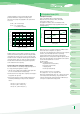
Conductive polymer Type Feature EMC Lead Frame Precautions in using Tantalum Capacitors 4 Characteristics Explanation Tantalum wire Tantalum Power Positive C / Ag Conductive polymer Ta2O5 Dielectric Negative SCN Series Configuration And Dimension SCS Series Normal type W1 L Z Z H SCS-P Series W2 SCM Series Unit : mm Case Code EIA Code L W1 W2 H Z P 2012 2.0±0.2 1.25±0.2 0.9±0.1 1.2 max 0.5±0.2 T 3528L 3.2±0.2 2.8±0.2 2.2±0.1 1.2 max 0.8±0.3 L 3528 3.5±0.2 2.8±0.2 2.
Conductive Polymer Type Series System Diagram PCS Extended series PCL Low Profile Uitra-Low ESR type Low ESR type Low Profile
PCS (Conductive Polymer Tantalum Chip Capacitors) Feature The Polymer Capacitor(PCS Series) have inherently low ESR(equivalent series resistance) and are capable of higher ripple current handling, producing lower ripple voltages, less power and heat dissipation than standard product for the most efficient use of circuit power. The Polymer Capacitor has the same structure as a Mn02 type chip tantalum capacitor. It has conductive polymer cathode as a substitute for Mn02 type.
PCL (Low-Profile Conductive Polymer Tantalum Chip Capacitors) Feature - Low -Profile case size - Reduced thickness up to 63% of PCS series - Compatible with automatic pick and place equipment. - Terminations: 100 % Sn , RoHS Compliant Specifications Range Tolerance Capacitance 47㎌ ±20%(M) Refer to Specification Refer to Specification 6.3 6.3 5.0 8.0 6.
Marking Specification A, B, C, D, S, T Case A, S(Low-Profile) case SCN, SCS, SCE series SCL series A336 A336 Capacitance Code in ㎊ Rated Voltage (G: 4V J: 6.
P, R Case P, R(Low-Profile) case SCS series SCL series AA AA Capacitance Code (A: 1.0 E: 1.5 J: 2.2 N: 3.3 S: 4.7 W: 6.8) Rated Voltage (G: 4V J: 6.3V A: 10V C: 16V D: 20V) Polarity (White) Code Reference V 4 6.3 10 16 0.22 gj jj aj cj 0.47 gs js as cs ds 0.68 gw jw aw cw dw 1.0 Ga Ja Aa Ca 2.2 Gj SJ Aj Cj 3.3 Gn Jn An 4.7 Gs Js As 6.8 Gw Jw 10 GA JA 22 GJ JJ ㎌ 1.
J, Q, K Case 1608 case (SCM series) Q case Precautions in using Tantalum Capacitors z z J case 4 Characteristics Explanation Voltage, Capacitance Polarity (White) SCN Series K case GA SCS Series Capacitance Code SCS-P Series Rated Voltage (G:4V J:6.3V A:10V C:16V D:20V) Polarity (White) SCM Series J, Q(Low-Profile) Case Code Reference V ㎌ 4 1.0 SCF Series K Case Code Reference V 6.3 10 16 a B C 1.0 ㎌ 4 6.3 10 16 SCE Series 1.5 D E F G 1.5 2.2 I J K L 2.2 3.
Conductive Polymer Type P case + As Capacitance Code (A:1.0 E: 1.5 J: 2.2 N: 3.3 S: 4.7 W:6.8) Rated Voltage (G: 4V J: 6.3V A: 10V C: 16V D: 20V) Polarity (White Stripe) B, L, T case + 150 6V Capacitance (150㎌) Rated Voltage(6.
Face Down Type U case(1005mm size) I case(1005mm size) r Precautions in using Tantalum Capacitors r 4 Characteristics Explanation Rated Voltage, Capacitane Code Rated Voltage, Capacitane Code Polarity RV ㎌ SCN Series 4 6.3 10 SCS Series 1.0 a 2.2 j SCS-P Series s SCM Series 3.3 4.
Taping Specification Taping Specification The tantalum chip capacitors shall be packaged in tape and reel from for effective use. Cover Tape F 15。 Tape: Semitransparent embossed plastic Cover tape: Attached with press, polyester The tension of removing the cover tape, F=10~70g Romoval Speed 50mm/sec Carrier Tape Dimension Right hand Orientation available Embossed D1 Embossed Carrier E W F A B D2 t P0 P1 P2 K Direction of Feed EMBOSSED PLASTIC TAPE Case Code W±0.3 F±0.1 E±0.
Reel Dimension E Precautions in using Tantalum Capacitors C B C 4 Characteristics Explanation D SCN Series A t W SCS Series Unit: mm Symbol Tape Width A B C D 8mm Ø180+0/-3 Ø60+1/-0 Ø13±0.3 Ø4±0.2 12mm Ø180+0/-3 Ø60+1/-0 Ø13±0.3 Ø4±0.2 8mm Ø330±2.0 Ø80±1.0 Ø13±0.3 Ø4±0.2 12mm Ø330±2.0 Ø80±1.0 Ø13±0.3 Ø4±0.2 7" Reel 13" Reel Symbol Tape Width E W t 8mm 2.0±0.5 9±0.5 1.2±0.2 12mm 2.0±0.5 13±0.5 1.2±0.2 8mm 2.0±0.5 9±0.5 2.2±0.2 12mm 2.0±0.5 13±0.
Packaging Table General type Inner Box Outer Box 30±1.0 Front 185±1.0 197±5.0 Front 352±5.0 66±1.0 180±1.0 375±5.0 Polymer type Inner Box Outer Box 25±1.0 Front 220±1.0 229±3.0 Front 355±3.0 68±1.0 230±1.0 Taping Packaging TYPE Inch (Unit : mm) 475±3.
34 42 35 43
Passive components sales offices ● Head office Philippines Plant (Philippines) Block No.5, Calamba Premiere International Park, Batino, Calamba, Laguna, Manila, Philippines 4027 Te l:+63 - 49- 545- 0422 E-mail:donna@samsung.com 206, Cheomdansaneop Road, Yeongtong-gu, Suwon-city, Gyeonggi province, Korea, 443- 743 Europe Te l:+82- 31- 210 - 6328 E-mail:james.pyun@samsung.com America Te l:+82- 31- 210 - 6803 E-mail:wesley.roh@samsung.com Asia Te l:+82 - 31- 210 - 6791 E-mail:peter_kim@samsung.