
Datasheet


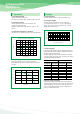

Ambient
temperature(℃)
J,Q,K
25
55
85
0.015
0.010
0.005
0.015
0.010
0.005
0.030
0.019
0.010
0.030
0.019
0.010
0.030
0.019
0.010
0.050
0.032
0.018
P,R A,S B,T C D
0.015
0.010
0.005
U
PMAX(W)
Frequency
120
400
1k
10k
20k
40k
100k
1M
1.0
0.8
0.65
0.50
0.45
0.43
0.40
0.35
K
Tan δ
2πfC
20%
0
40%
60%
80%
100%
-40 -20-55 0 40 60
20
80
100
125
Operating temperature(℃)
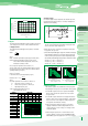
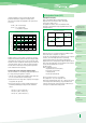
Fig. 3
Recommended range
Upper limit
Voltage delating
(rated voltage × %)
2. Ripple
The maximum permissible ripple voltage and current are related
to the ratings case size. Please consult us detail informations.
2.1 Ripple Current
The maximum permissible ripple current, IMAX, is calculated
as follows:
IMAx =
√
PMAX
ESR(f)
K-factor
0.01
0.1
1.0
10
100 1K 10K 100K 1M
Frequency (Hz)
Fig. 4 Correction coefficient(K)
4
5
where:
IMAX : Maximum permissible capacitor ripple current (Arms).
PMAX : Maximum permissible capacitor power loss (W).
Varies with the ambient temperature and case size.
Calculated according to Table 1.
ESR (f ): Capacitor equivalent series resistance (Ω).
Since the ESR(f) value varies with the ripple frequency, however,
the following correction must be made in accordance with the
operating frequency (see Fig. 4).
ESR(f) = K
•
ESR(120)
K: Coefficient for the operating frequency ( Fig. 4).
ESR(120) = Tan δ
•
Xc =
where:
ESR (120) : Equivalent series resistance at 120 Hz (Ω).
Xc : Capacitive reactance at 120 Hz (Ω).
C : Electrostatic capacitance at 120 Hz (μF).
f : Operating frequency (Hz).
Precautions in using
Tantalum Capacitors
4 Characteristics
Explanation
SCN Series
SCS Series
SCS-P Series
SCM Series
SCF Series
SCE Series
Taping
Specification
Marking
Specification
SCL Series
PCS Series
PCL Series
0.1
1
10
100
0.1 1 10 100
Maximum permissible
ripple voltage
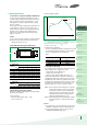
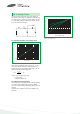
Fig. 6 Maximum permissible
ripple voltage(P, A, B)
Frequency
Fig. 7 Maximum permissible
ripple voltage(C, D)
Frequency
Case size
P, A, B
UA, UB
@25
℃
Case size
C, UE, E
F, UC
@25
℃
1) The tantalum capacitors must be used in such a conditions that
the sum of the Working voltage and ripple voltage peak values
does not exceed the rated voltage (Fig. 5)
2) Ensure that an reverse voltage due to superimposed voltages is
not applied to the capacitors.
3) The maximum permissible ripple voltage varies with the rated voltage.
Ensure that ripple voltage does not exceed the values shown in Figs.
6 and 7. If, however, the capacitors are used at a high temperature,
the maximum permissible ripple voltage must be calculated as follows:
Vrms(at 55℃) = 0.7
×
Vrms(at 25℃)
Vrms(at 85℃) = 0.5
×
Vrms(at 25℃)
Vrms(at 125℃) = 0.3
×
Vrms(at 25℃)
3. Reverse Voltage
Solid tantalum capacitors are polarized device and may be perma-
nently damaged or destroyed, if connected with the wrong polarity.
1) The tantalum capacitors must not be operated and changed
inreverse mode. And also the capacitors must not be used in
an only AC circuit.
2) The tantalum capacitor dielectric has a rectifying characteristics.
Therefore, when a reverse voltage is applied to it, a large current
flows even at a low reverse voltage.As a result,it may spontan-
eously generate heat and lead to shorting.
3) Make sure that the polarity and voltage is correct when
applying a multimeter or similar testing instrument to the
capacitors because a reverse voltage or overvoltage can be
accidentally applied.
4) When using the capacitors in a circuit in which a reverse
voltage is applied, consult your local SAMSUNG ELECTRO-
MECHANICS agent. If the application of an reverse voltage is
50V
35V
25V
20V
16V
10V
6.3V/7V
4V
2.5V
0.1
1
10
100
0.1 1 10 100
50V
35V
25V
20V
16V
10V
6.3V/7V
4V
2.5V
2.2 Ripple Voltage
If an excessive ripple voltage is applied to the tantalum capacitors,
their internal temperature rises due to Joule heat, resulting in the
detriment of their reliability.
Time (sec)
Fig. 5
Voltage
Operating
Voltage
Rating Voltage
Ripple Voltage
Working Voltage
Table 1 Maximum permissible power loss
values (PMAX) by case size