
Datasheet

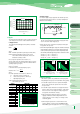


Operating Temperature (T)
120
110
100
90
80
70
60
50
40
30
20
T
Connect the temperature
and applied voltage ratio
of interest with a straight
edge. The multiplier of
failure rate is given at the
intersection of this line with
the model scale.
Given T1&V1 Read failure rate
multiplier F1
Given T&F2 Read voltage V2
Given F3&V3 Read allowable
temp T3
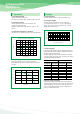
Fig. 9 Reliability Nomograph
Circuit Impedance
(ohms / volt)
0.1
0.2
0.4
0.6
0.8
1.0
2.0
3 or greater
Failure Rate Impedance
(multiplying factor)
1.0
0.8
0.6
0.4
0.3
0.2
0.1
0.07
FV
10
2
10
1
10
0
10
-1
10
-2
10
-3
10
-4
10
-5
1.0
0.7
0.5
0.4
0.3
0.2
0.1
Failure Rate Multiplier (F)
Applied Voltage Ratio (V/VO)
4.3 Reliability Prediction
Solid tantalum capacitors exhibit no degration failure mode
during shelf storage and show a constantly decreasing failure
rate(i.e., absence of wearout mechanism) during life tests.
This failure rate is dependent upon three important application
conditions:DCvoltage, temperature, and circuit impedance.
Estimates of these respective effects are provided by the reliability
nomograph.(Figure 9.)
The nomograph relates failure rate to voltage and temperature
while the table relates failure rate to impedance.
These estimates apply to steady-state DC condition, and they
assume usage within all other rated conditions.
Standard conditions, which produce a unity failure rate factor,
are rated voltage, +85
℃, and 0.1 ohm-per-volt impedance.
While voltage and temperature are straight-forward, there is some-
times difficulty in determining impedance. What is required is the
circuit impedance seen by the capacitor. If several capacitors are
connected in parallel, the impedance seen by each is lowered by
the source of energy stored in the other capacitors. Energy is sim-
ilarly stored in series inductors.
It is possible to lose more via higher inherent failure rate than
is gained by voltage derating. SAMSUNG typically recommends
50% derating, especially in low impedance circuits.
Failure rate is conventionally expressed in units of percent per
thousand hours. As a sample calculation, suppose a particular
batch of capacitors has a failure rate of 0.5%/ Khr under sta-
ndard conditions.
What would be the predicted failure rate at 0.7times rated voltage,
60℃ and 0.6Ω/V?
The nomgraph gives a factor of 7
×
10
-2
and the table gives a
factor of 0.4.
The failure rate estimate is then :
0.5
×
7
×
10
-2
×
0.4 = 1.4
×
10
-2
or 0.014%/ Khr
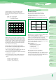
Table 4 Circuit Impedance Reliability Factors
·
Failure rate calculation formula
λuse = λ85
×
K
V
×
K
R
λuse: Estimated capacitor failure rate under the operating
conditions.
λ85: Basic failure rate (Table 3)
K
V: Failure rate correction coefficient by the ambient
temperature and derating factor.
K
R: Failure rate correction coefficient by the circuit resistance,
which is the series-connected resistance divided by the
voltage applied to the capacitor. This resistance is connected
in series when the power supply side is viewed from
the capacitor side.
K (derating factor)=operating voltage/rated voltage
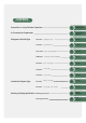
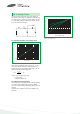
Type Classification
Face - down type
Low ESR type
Ultra-Miniature type (0603)
Low profile type
Small type
Standard type
Conductive Polymer type
1%/1000h
Basic failure rate
SCF
SCE
SCM
SCL
SCS
SCN
PCS,PCL
unavoidable, it must not exceed the following values:
At 20°C: 10% of the rated voltage of 1 V, whichever smaller.
At 85°C: 5% of the rated voltage or 0.5 V, whichever smaller.
4. Reliability of Tantalum Capacitors
4.1 General
The failure rate of the tantalum capacitor varies with the derating
ratio, ambient temperature, circuit resistance, circuit application,
etc. Therefore, when proper selections are made so as to afford
additional margins, higher reliabilities can be derived from the
tantalum capacitors. Some examples of actual failure rates are
presented below for your reference.
4.2 Failure Rate Calculation Formula
The tantalum capacitors are designed to work at their basic
failure rates shown in Table 3 that prevail when the rated voltage
is applied for 1000 hours at 85℃.
Table 3 Basic failure rate
Voltage “de-rating” is a common and useful approach to improved
reliability. It can be persued too far, however, when it leads to in-
stallation of higher voltage capacitors of much larger size.