
Datasheet
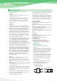


5. Mounting Precautions
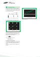
5.1 Limit Pressure on Capacitor Installation with Mounter
A capacitor that has been damaged should be discarded to
avoid later problems resulting from mechanical stress. Pressure
must not exceed 4.9 N with a tool end diameter of 1.5 mm
when applied to the capacitors using an absorber, centering
tweezers, or the like.
An excessively low absorber setting position would result in not
only the application of undue force to the capacitors but
capacitor and other component scattering,circuit board wiring
breakage, and / or cracking as well, particularly when the
capacitors are mounted together with other chips having a
height of 1 mm or less.
5.2 Flux
(1) Select a flux that contains a minimum of chlorine and amine.
(2) After flux use, the chlorine and amine in the flux remain
and must therefore be removed.
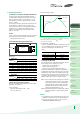
5.3 Recommended Soldering Pattern Dimensions
Pattern
Capacitor
Fig. 10
L
zx
y
W
x
6
7
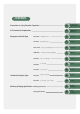
Precautions in using
Tantalum Capacitors
4 Characteristics
Explanation
SCN Series
SCS Series
SCS-P Series
SCM Series
SCF Series
SCE Series
Taping
Specification
Marking
Specification
SCL Series
PCS Series
PCL Series
5.5 Cleaning after Mounting
The following solvents are usable when cleaning the capacitors
after mounting. Never use a highly active solvent.
·Halogen organic solvent (HCFC225, etc.)
·Alcoholic solvent (IPA, ethanol, etc.)
·Petroleum solvent, alkali saponifying agent, water, etc.
Circuit board cleaning must be conducted at a temperature of
not higher than 50°C and for an immersion time of not longer
than30 minutes. When an ultrasonic cleaning method is used,
cleaning must be conducted at a frequency of 48 kHz or lower,
at an vibrator output of 0.02 W/cm3, at a temperature of not
higher than 40°C, and for a time of 5 minutes or shorter.
NOTE 1: Care must be exercised in cleaning process so that the
mounted capacitor will not come into contact with any
cleaned object or the like or will not get rubbed by a
stiff brush or the like. If such precautions are not taken
particularly when the ultrasonic cleaning method is
employed, terminal breakage may occur.
NOTE 2: When performing ultrasonic cleaning under conditions
other than stated above, conduct adequate advance
checkout.
(1) For further details, refer to EIAJ RCR-2368, Precautions and
Guidelines for Using Electronic Device Tantalum Capacitors.
(2) If you have any questions, feel free to contact your local
SAMSUNG ELECTRO-MECHANICS agent.
6. Other
General type
5.4 Chip Soldering Temperature and Time
Capacitors are capable of withstanding the following soldering
temperatures and conditions;
(1) Waved soldering
Capacitor body temperature: 230℃∼ 260℃
Time: 5 seconds or less
(3) Soldering with a soldering iron
The use of a soldering iron should be avoided wherever possible
If it is unavoidable, follow the instructions set forth in Table 5.
The time of soldering with an iron should be one.
Table 5
Dimensions
Case
J,Q,K
P,R
A,S
B,T
C,V
D,W
1.6
2.0
3.2
3.5
5.8
7.3
0.85
1.25
1.6
2.8
3.2
4.3
0.9
1.2
1.6
1.6
2.3
2.3
1.0
1.1
1.2
2.2
2.4
2.6
0.7
0.8
1.2
1.4
2.4
3.8
Capacitors size
L W x y z
Pattern dimensions
Face - down type
Dimensions
Case
U 1.0 0.5 0.3 0.4 0.65
Capacitors size
L W x y z
Pattern dimensions
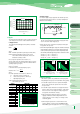
FIGURE: Typical Temperature Profile of Reflow Soldering for
Pb-free Products (235℃~245℃, Recommendation Temperature)
With Pb-free products, if used under 235 , the quality
confirmation must be needed.
100
200
100 000
20 30
40
Temp.
(℃)
Time (sec)
Heating
260℃ Max
Cooling
Pre-heating
Tape
350℃
MAX
3sec MAX
30W
MAX
All case
Soldering-iron tip temperature
Time
Soldering-iron power
(2) Reflow soldering see figures