
Datasheet
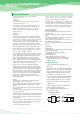


4 Characteristics
Explanation
1-1. Rated Capacitance(CR)
This is the nominal rated capacitance.
capacitance is measured at 120㎐, 1.0V RMS, DC Bias 1.0V~2.0V
1-2. Capacitance tolerance
This is the permissible variation of the actual value of the
capacitance from the rated value.
Available in standard EIA nominal values with ±20% & ±10%
tolerance.
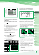
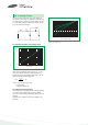
1-3. Temperature dependence of capacitance.
The capacitance of a tantalum capacitance varies with temperature.
1-4. Frequency dependence of capacitance
The effective capacitance decrease as frequency increases.
Beyond 100㎑ the capacitance continues to drop until resonance
is reached.
15
10
5
0
-5
-10
-15
-55 -25 0 25 50 75 100 125
Temperature(℃)
TYPICAL CAPACITANCE
VS. TEMPERATURE
% Capacitance
250
200
150
100
50
0
100 1000 10000 100000 1000000
Frequency(㎐)
CAPACITANCE VS. FREQUENCY
Capacitance(㎌)
1. Capacitance 2. Voltage
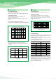
2-1. Rated voltage(VR)
This is the rated d.c. voltage for continuous operation at 85℃.
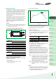
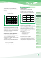
2-2. Category voltage(V
C)
Tantalum capacitors are designed to operate continuously
over the temperature range of -55℃ to +85℃ with operating
voltage. these capacitance may be operated at 125℃ with 2/3
derated voltage as shown in fig.
2-3. Surge voltage(V
S)
Surge voltage is the maximum voltage to which the capacitor can
be subjected under transient conditions: including the sumof peak
AC ripple, DC bias and any transients.
the surge voltage must not be used as a parameter in the design
of circuits in which, in the normal course of operation, the capacitor
is periodically charged and discharged.
2-4. Reverse voltage and polarity.
Solid tantalum capacitors are polarized device and may be perm-
anently damaged or destryed if connected with the wrong polarity.
They are intended to cover short term reversals of polarity, such
as those occuring during switching transients of during a minor
portion of an impressed waveform.
85℃
Rated
Voltage(Vdc)
Surge
Voltage(Vdc)
125℃
2.5
4
6.3
10
16
20
25
35
50
3.1
5.2
8
13
20
26
32
46
65
Category
Voltage(Vdc)
Surge
Voltage(Vdc)
1.6
2.7
4
4
10
13
17
23
33
2.0
3.52
5
8
12
16
20
28
40
100%
80%
60%
40%
20%
-40 0 40 80 120
Operating Temperature(℃)
Figure 1 Working DC Voltage Change With Temperature