
Datasheet


8
9
Precautions in using
Tantalum Capacitors
4 Characteristics
Explanation
SCN Series
SCS Series
SCS-P Series
SCM Series
SCF Series
SCE Series
Taping
Specification
Marking
Specification
SCL Series
PCL Series
PCS Series
continuous application of reverse voltage without normal
polarization will result in a degration of leakage current.
The peak reverse polarity voltage applied to the capacitor must
not exceed:
at +20℃, 10% of rated voltage
at +85℃, 5% of rated voltage
or 1V,whichever is greater.
If higher voltages of reverse polarity occur, then two capacitors
with the same norminal capacitance and rated voltage should be
connected in series in such a way as to form a non-polar combi-
nation(back-to-back configuration with the negative terminations
connected together). when d.c. voltage are switched, measures
must be taken to ensure that the reverse polarized capacitance
avoid a reduction in its life expectancy.
2-5.Super imposed A.C. voltage(V
r.m.s) Ripple voltage.
This is the maximum r.m.s alternating voltage ;superimposed on a
d.c. voltage, that may be applied to a capacitor.
1) The sum of the working voltage and ripple voltage peak value
does not exceed the rated d.c working voltage.
2) Ensure that an reverse voltage due to super imposed voltages is
not applied to the capacitors.
3) If,hoeever,the capacitors are used at a high temperature, the
maximum permissible ripple voltage must be calculated as
follows :
Vrms (at 55℃) =0.7×Vrms(at 25℃)
Vrms (at 85℃)=0.5×Vrms(at 25℃)
Vrms (at 125℃)=0.3×Vrms(at 25℃)
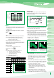
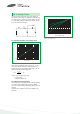
3.Dissipation factor (D.F.)
Refer to part number tables for maximum DF limits.
Dissipation factor is measured at 120 Hz, 1.0Volt RMS
and 1.0~2.0 volts DC at +25℃.
The application of dc bias causes a small reduction in DF,
about 0.2% when full rated voltage is applied DF increases with
increasing frequency.
Dissipation factor is a very useful low frequency (120hz) measure-
ment of the resistive component of a capacitor.
It is the ratio of the equivalent series resistance(esr) to the capacitive
reactance, (Xc) and is usually expressed as a percentage.
It is directly proportional to both capacitance and frequency.
dissipation factor loses its importance at higher frequencies, (above
about 1 khz), when impedance. (z) and equivalent series resistance
(esr) are the normal parameters of concern.
DF= R/Xc =2πfCR
where DF=dissipation factor
R=equivalent series resistance(ohms)
Xc=capactive reactance(ohms)
f =frequency(hertz)
C=series capacitance(farads)
DF is also referred to as tanδor “loss tangent.”
The “quality factor” “Q” is the reciprocal of DF.
DF increases with temperature above +25℃ and may also increase
at lower temperatures. Unfortunately, one general limit for DF
cannot be specified for all capacitance/voltage combinations, nor
can response to temperature be simply stated.
10
8
6
4
2
0
-2
-4
-6
-8
-10
-20 0 20 40 60 80 100
Applied Voltage(Volts)
LEAKAGE CURRENT
VS. BIAS VOLTAGE
Leakage Current(㎂)
50
5
1
0.1
0.1 1 10 100
Frequency(kHz)
TYPICAL DF vs FREQUENCY
DF Multiplier
3. Dissipation Factor (D.F.)