SyncMaster 400MP,460MP,400MPn, 460MPn LCD Monitor User Manual
Safety Instructions Notational Note These safety instructions must be followed to ensure your safety and prevent property damage. Make sure to read the instructions carefully and use the product in the correct manner. Warning / Caution Failure to follow directions noted by this symbol could result in bodily harm or damage to the equipment.
Safety Instructions Do not forcefully bend or pull the power plug and do not place any heavy material on it. • Otherwise, this may result in fire. Do not connect multiple appliances to the same power outlet. • Otherwise, this may cause fire due to overheating. Do not disconnect the power cord while using the product. • Otherwise, this may result in damage to the product due to electric shock.
Safety Instructions Do not install it in a badly ventilated location such as a bookcase or closet. • Otherwise, this may result in fire due to an increase in the internal temperature. When putting the product down, make sure to put it down softly. • Otherwise, this may result in damage to the screen display. Do not place the front of the product on the floor. • Otherwise, this may result in damage to the screen display. Ensure that an authorized installation company installs the wall mount.
Safety Instructions When cleaning the product, make sure to disconnect the power cord. • Otherwise, it may result in electric shock or fire. When cleaning the product, disconnect the power cord and clean it softly with a dry cloth. • (Do not use chemicals such as wax, benzene, alcohol, thinner, mosquito repellant, lubricant, or cleaner.) These may change the appearance of the product surface and peel off the indication labels on the product.
Safety Instructions Do not try to move the monitor by pulling only the wire or the signal cable. • Otherwise, it may fall and result in electric shock, damage to the product or fire due to damage to the cable. Do not lift or move the product back and forwards or right and left while only holding the power cord or signal cables. • Otherwise, it may fall and result in electric shock, damage to the product or fire due to damage to the cable.
Safety Instructions Take a rest for at least five (5) minutes after using the monitor for one (1) hour. This reduces the weariness of your eyes. Do not install it in an unstable location such as an unstable rack or uneven surface or a location exposed to vibrations. • Otherwise, it may fall and cause personal injury and/or damage the product. • If you use the product in a location exposed to vibrations, it may damage the product and result in fire.
Safety Instructions Do not place the product in a location exposed to direct sunlight or near any heat such as a fire or heater. • This may reduce the lifetime of the product, and may result in fire. Do not drop any objects onto the product or cause any impact to the product. • Otherwise, this may result in electric shock or fire. Do not use a humidifier or kitchen table near the product. • Otherwise, this may result in electric shock or fire.
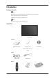
Introduction Package Contents Note Please make sure the following items are included with your LCD Display. If any items are missing, contact your dealer. Contact a local dealer to buy optional items. Note This stand is not for the Floor Standing Type.
Introduction Others Remote Control Batteries (AAA X 2) HDD Cover (Not available in all locations) BNC to RCA Adaptor Jack Sold separately DVI Cable Wall Mount KIT LAN Cable (Applicable to the MPn model only) TV tuner box NetWork Box Semi Stand KIT (Applicable to the MP model only) BNC Cable Note • You can purchase and connect a separate network box or TV tuner box. For information on how to use these, refer to their respective user manuals. • You can only connect one external box.
Introduction Your LCD Display Front MENU button [MENU] Opens the on-screen menu and exits from the menu. Also use to exit the OSD menu or return to the previous menu. Navigate buttons (Up-Down buttons) Moves from one menu item to another vertically or adjusts selected menu values. Adjust buttons (Left-Right buttons) / Volume buttons Moves from one menu item to another horizontally or adjusts selected menu values. When OSD is not on the screen, push the button to adjust volume.
Introduction Use this button for turning the LCD Display on and off. Power indicator Shows PowerSaver mode by blinking green Note See PowerSaver described in the manual for further information regarding power saving functions. For energy conservation, turn your LCD Display OFF when it is not needed or when leaving it unattended for long periods. Remote Control Sensor Aim the remote control towards this spot on the LCD Display.
Introduction RS232C OUT/IN (RS232C Serial PORT) MDC(Multiple Display Control) Program Port DVI / PC / HDMI IN [DVI/PC/HDMI AUDIO IN] (PC/DVI/HDMI Audio Connection Terminal (Input)) DVI / PC / HDMI IN [HDMI] Connect the HDMI terminal at the back of your LCD Display to the HDMI terminal of your digital output device using a HDMI cable.
Introduction BNC/COMPONENT OUT[R/PR, G/Y, B/PB, H, V] (BNC/Component Connection Terminal (Output)) BNC (Analog PC) Connection: connecting the R, G, B, H, V ports. Component Connection: connecting the PR, Y, PB ports. BNC/COMPONENT IN[R/PR, G/Y, B/PB, H, V] (BNC/Component Connection Terminal (Input)) RGB OUT (Applicable to the MPn model only) LAN (LAN Connection Terminal) (Applicable to the MPn model only) USB(USB Connection Terminal) Keyboard / Mouse, Mass Storage Device Compatible.
Introduction Kensington Lock The Kensington Lock is a device used to physically fix the system when using it in a public place. The locking device has to be purchased separately. The appearance and locking method may differ from the illustration depending on the manufacturer. Refer to the manual provided with the Kensington Lock for proper use. The locking device has to be purchased separately. Note The location of the Kensington Lock may be different depending on its model.
Introduction POWER OFF Number Buttons DEL button + VOL MUTE TV/DTV MENU INFO COLOR BUTTONS TTX/MIX STILL AUTO S.MODE MDC LOCK SOURCE ENTER/PRE-CH CH/P D.MENU GUIDE RETURN Up-Down Left-Right buttons EXIT SRS MagicInfo P.MODE DUAL/MTS PIP SWAP 1. POWER Turns the product On. 2. Off Turns the product Off. 3. Number Buttons Press to change the channel.
Introduction 4. DEL button 5. + VOL 6. The "-" button operates only for DTV. It is used to select MMS (multi-channel) for a DTV. Adjusts the audio volume. MUTE Pauses (mutes) the audio output temporarily. This is displayed on the lower left corner of the screen. The audio resumes if MUTE or - VOL + is pressed in the Mute mode. 7. TV/DTV Selects the TV and DTV mode directly. 8. Opens the on-screen menu and exits from the menu or closes the adjustment menu. MENU Activates a highlighted menu item.
Introduction 24. Up-Down Left-Right buttons Moves from one menu item to another horizontally, vertically or adjusts selected menu values. 25. EXIT Exits from the menu screen. 26. SRS Selects SRS TruSurround XT mode. 27.MagicInfo MagicInfo Quick Launch Button. 28. P.MODE When you press this button, current picture mode is displayed on the lower center of the screen. AV / HDMI / TV : P.MODE The LCD Display has four automatic picture settings that are preset at the factory.
Introduction
Introduction LCD Display Head NETWORK MODEL SIZE Installation VESA Bracket • When installing VESA, make sure to comply with the international VESA standards. • Purchasing VESA Bracket and Installation Information : Please contact your nearest SAMSUNG Distributor to place an order. After your order is placed, installation professionals will visit you and install the bracket. • At least 2 persons are needed in order to move the LCD Display.
Introduction Dimensions Notice For securing the bracket on a wall, use only machine screws of 6 mm diameter and 8 to 12 mm length. Wall Bracket Installation • Contact a technician for installing the wall bracket. • SAMSUNG Electronics is not responsible for any damages to the product or harm to customers when the installation is done by the customer. • This product is for installing on cement walls. The product may not stay in place when installed on plaster or wood.
Introduction When done, mount the wall bracket on the wall. There are two hinges(left and right). Use the correct one. 2. A- Captive Screw B- Wall Bracket C- Hinge (Left) D- Hinge (Right) Before drilling into the wall, check if the length between the two locking holes at the back of the product is correct. If the length is too short or long, loosen all or some of the 4screws on the wall bracket to adjust the length. A3.
Introduction To mount the product on the wall bracket The shape of the product may vary depending on the model. (The assemblies of the plastic hanger and the screw are the same) 1. Remove the 4 screws on the back of the product. 2. Insert the screw B into the plastic hanger. Notice 3. • Mount the product on the wall bracket and make sure it is properly fixed to the left and right plastic hangers. • Be careful when installing the product on the bracket as fingers can be caught in the holes.
Introduction 4. Remove safety pin (3) and insert the 4 product holders into the corresponding bracket holes (1). Then place the product(2) so that it is firmly fixed to the bracket. Make sure to re-insert and tighten the safety pin (3) to securely hold the product to the bracket. A- LCD Display B- Wall Bracket C- Wall Wall Bracket Angle Adjustment Adjust the bracket angle to -2° before installing it on the wall. 1. Fix the product to the wall bracket. 2.
Introduction Make sure to use the top center, and not the leftor the right side of the product to adjust the angle.
Connections Connecting a Computer Using a Power cord with Earth • In the event of failure, the earth lead may cause electric shock. Make sure to wire the earth lead in correctly, before connecting the AC power. When unwiring the earth lead, make sure to disconnect the AC power in advance. Note AV input devices such as DVD players, VCR's or camcorders as well as your computer can be connected to the LCD Display.
Connections Using the BNC (Analog) connector on the video card. • Connect the BNC Cable to the BNC/COMPONENT IN - R, G, B, H, V ports on the back of your LCD Display and the 15 pin D-sub Port on the computer. Connect the audio cable for your LCD Display to the audio port on the back of your computer. Note • Turn on both your computer and the LCD Display. • The DVI cable is optional. • Contact a local SAMSUNG Electronics Service Center to buy optional items.
Connections 3. Select AV using the SOURCE . Note The LCD Display has AV connection terminals to connect AV input devices like DVDs, VCRs or Camcorders. You may enjoy AV signals as long as the LCD Display is turned on. Connecting to a Camcorder 1. Locate the A/V output jacks on the camcorder. They are usually found on the side or back of the camcorder. Connect a set of audio cables between the AUDIO OUTPUT jacks on the camcorder and the AV AUDIO IN [L-AUDIO-R] on the LCD Display . 2.
Connections 2. Connect a Component cable between the BNC/COMPONENT IN - PR, Y, PB port on the LCD Display and the PR, Y, PB jacks on the DVD player. Note • Select Component for the connection to a DVD player using the SOURCE button on the front of the LCD Display or on the remote control. • Then, start the DVD Player with a DVD disc inserted. Note • A component cable is optional. For an explanation of Component video, consult your DVD manual.
Connections Connecting Using a HDMI Cable Note • Input devices such as digital DVD are connected to the HDMI terminal of the LCD Display using the HDMI cable. • You cannot connect a PC to the HDMI terminal. Connecting Using a DVI to HDMI Cable Note • Connect the DVI output terminal of a digital output device to the HDMI terminal of the LCD Display using a DVI to HDMI cable.
Connections Connecting a LAN Cable Using a Power cord with Earth • In the event of failure, the earth lead may cause electric shock. Make sure to wire the earth lead in correctly, before connecting the AC power. When unwiring the earth lead, make sure to disconnect the AC power in advance. Note AV input devices such as DVD players, VCR's or camcorders as well as your computer can be connected to the LCD Display.
Connections Note You can connect USB devices such as a mouse or keyboard.
Using the Software Monitor Driver Note When prompted by the operating system for the monitor driver, insert the CD-ROM included with this monitor. Driver installation is slightly different from one operating system to another. Follow the directions appropriate for the operating system you have. Prepare a blank disk and download the driver program file at the Internet web site shown here. Internet web site : http://www.samsung.com/ (Worldwide) Installing the Monitor Driver (Automatic) 1.
Using the Software Note This monitor driver is under certifying MS logo, and this installation doesn't damage your system. The certified driver will be posted on Samsung Monitor homepage. http://www.samsung.com/ Installing the Monitor Driver (Manual) Microsoft® Windows Vista™‚ Operating System 1. Insert your Manual CD into your CD-ROM drive. 2. Click 3. Click "Personalization" and then "Display Settings". 4. Click "Advanced Settings...". 5. Click "Properties" in the "Monitor" tab.
Using the Software Note This monitor driver is under certifying MS logo, and this installation doesn't damage your system. The certified driver will be posted on Samsung Monitor homepage. 6. Click "Update Driver..." in the "Driver" tab. 7. Check the "Browse my computer for driver software" checkbox and click "Let me pick from a list of device drivers on my computer". 8. Click "Have Disk...” and select the folder (for example, D:\Drive) where the driver setup file is located, and click "OK".
Using the Software 9. Select the model that matches your monitor from the list of monitor models on the screen, and click "Next". 10. Click "Close" → "Close" → "OK" → "OK" on the following screens displayed in sequence.
Using the Software 1. Insert CD into the CD-ROM drive. 2. Click "Start" → "Control Panel" then click the "Appearance and Themes" icon. 3. Click "Display" icon and choose the "Settings" tab then click "Advanced...". 4. Click the "Properties" button on the "Monitor" tab and select "Driver" tab. 5. Click "Update Driver..." and select "Install from a list or..." then click "Next" button. 6. Select "Don't search, I will..." then click "Next" and then click "Have disk".
Using the Software 7. Click the "Browse" button then choose A:(D:\Driver) and choose your monitor model in the model list and click the "Next" button. 8. If you can see following message window, then click the "Continue Anyway" button. Then click "OK" button. Note This monitor driver is under certifying MS logo, and this installation doesn't damage your system. The certified driver will be posted on Samsung Monitor homepage. http://www.samsung.com/ 9.
Using the Software 10. Monitor driver installation is completed. Microsoft® Windows® 2000 Operating System When you can see "Digital Signature Not Found" on your monitor, follow these steps. 1. Choose "OK" button on the "Insert disk" window. 2. Click the "Browse" button on the "File Needed" window. 3. Choose A:(D:\Driver) then click the "Open" button and then click "OK" button. How to install 1. Click "Start", "Setting", "Control Panel". 2. Double click the "Display" icon. 3.
Using the Software 4. Select the "Monitor" tab. 5. Click the "Change" button in the "Monitor Type" area. 6. Choose "Specify the location of the driver". 7. Choose "Display a list of all the driver in a specific location..." then click "Next" button. 8. Click the "Have Disk" button. 9. Specify A:\(D:\driver) then click "OK" button. 10. Select "Show all devices" and choose the monitor that corresponds to the one you connected to your computer and click "OK". 11.
Using the Software Installation MagicInfo Pro Installation 1. Insert CD into the CD-ROM drive. 2. Click the MagicInfo Pro installation file. 3. When the Install Shield Wizard window appears, click "Next." 4. Select "I agree to the terms of the license agreement" to accept the terms of use. 5. You are required to log in to the MagicInfo Pro Server program. Please enter the password to login. The password cannot be changed when you are logged in.
Using the Software 6. Choose a folder to install the MagicInfo Pro program. 7. Click "Install.
Using the Software 8. The "Installation Status" window appears. 9. It is recommended restarting the system for the normal operation of the MagicInfo Pro Server program. Click "Finish".
Using the Software 10. When the installation is complete, the MagicInfo Pro executable icon appears on your desktop. 11. Double-click the icon to start the program. System Requirements Minimum CPU RAM Ethernet OS P1.8 256M 100M/1G Windows XP WMP 9 or Windows later 2000 (Service Pack 4) Recommen- P3.
Introduction A Multiple Display Control (MDC) is an application allowing various displays to be easily and simultaneously operated on a PC. RS-232C, a standard of serial communication, is used for the communication between a PC and a display. Therefore, a serial cable should be connected between the serial port on a PC and the serial port on a display. Main Screen Click Start > Program > Samsung > MDC System to start the program. Select a set to see the volume of the selected set within the slider.
Main Icons Select Button Remocon Info Grid Safety Lock Display Selection Port Selection Control Tools 1. Use the main icons to switch into each screen. 2. Allows you to enable or disable the remote control signal receiving function of the display unit. 3. Set the Safety Lock function. When setting the Lock function, you can only operate power and lock buttons on the remote control and set. 4. The setting for the PC Serial Port can change. The original value is COM1. 5.
1. The Multiple Display Control is originally set to COM1. 2. If any port other than COM1 is used, COM1 through COM4 can be selected in the Port Selection Menu. 3. If the exact port name that is connected to the PDP Display using a serial cable is not selected, communication will be unavailable. 4. The selected port is stored in the program and used for the next program as well. Power Control 1. Click Power Control of the main icons and the Power Control screen appears.
Info Grid shows some basic information necessary to Power Control. 1) (Power Status) 2) Input 3) Image Size 4) On Timer 5) Off Timer 2. Use the Select All button or Check Box to choose a display to control. Power Control allows controlling some of the functions of the selected display.
- Turns the power of the selected display On/Off. 2) Volume - Controls the volume level of the selected display. It receives the volume value of the selected display from the sets and displays it in the slider. (When you cancel the selection or choose Select All, the value returns to the default value 10) 3) (Mute On/Off) - Turns on/off the Mute function of the selected display. When selecting one set at a time, turn on the Mute function for the selected set.
Info Grid shows some basic information necessary to Input Source Control. 1) PC - Changes the Input Source of the selected display to PC. 2) BNC - Changes the Input Source of the selected display to BNC. 3) DVI - Changes the Input Source of the selected display to DVI. 4) TV - Changes the Input Source of the selected display to TV. 5) DTV - Changes the Input Source of the selected display to DTV. 6) AV - Changes the Input Source of the selected display to AV.
Info Grid shows some basic information necessary to Image Size Control. 1) ( Power Status) - Shows the power status of the current display. 2) Image Size - Shows the current Image Size of the display in use. 3) Input - Shows the current Input Source of the display in use. 4) Info Grid displays only the displays whose Input Source is PC, BNC, DVI. 5) PC Source - When you click Image Size, the PC Source tab first appear. - The Image Size Control button controls Image Size available for PC, BNC, DVI.
Info Grid shows some basic information necessary to Image Size Control. 1) Click the Video Source tab to adjust Image Size for TV, AV, S-Video, Component, DVI(HDCP), HDMI, DTV. Click Select All or use Check Box to select a display to control. 2) Info Grid displays only the display having TV, AV, S-Video, Component or DVI(HDCP) as input source. 3) Switch Image Size of the selected display randomly.
Info Grid shows some basic information necessary to Time Control. 1) Current Time - Set the current time for the selected display (PC Time). - To change the current time, first change the PC Time. 2) On Time Setup - Set the Hour, Minute, AM/PM of On Time Setup, Status, Source, Volume of the selected display. 3) Off Time Setup - Set the Hour, Minute, and AM/PM, Status for Off Time Setup of the selected display. 4) Shows the On Time settings. 5) Shows the Off Time settings.
Info Grid shows some basic information necessary to PIP Size Control. 1) PIP Size - Shows the current PIP Size of the display in use. 2) OFF - Turns off the PIP of the selected display. 3) Large - Turns on the PIP of the selected display and changes the size to Large. 4) Small - Turns on the PIP of the selected display and changes the size to Small. 5) Double 1 - Turns on the PIP of the selected display and changes the size to Double 1.
Info Grid shows some basic information necessary to PIP Source Control. 1) PIP Source - PIP Source can be controlled with turning on the PDP Display power. 2) PC - Changes the source of the PIP of the selected display to PC. 3) BNC - Changes the source of the PIP of the selected display to BNC. 4) DVI - Changes the source of the PIP of the selected display to DVI. 5) AV - Changes the source of the PIP of the selected display to AV.
Info Grid shows some basic information necessary to Settings Control. When each function is selected, the set value of the selected function is displayed in the slide.When selected, each function fetches the value for the set and displays it on the slide bar. When "Select All" is chosen, the default value is displayed. Changing a value in this screen will automatically change the mode to "CUSTOM." 1) Picture - Available only for TV, AV, S-Video, Component, HDMI, DTV.
1. Click Settings of the main icons and the Settings Control screen appears. Info Grid shows some basic information necessary to Settings Control. When each function is selected, the set value of the selected function is displayed in the slide. When selected, each function fetches the value for the set and displays it on the slide bar. When "Select All" is chosen, the default value is displayed. Changing a value in this screen will automatically change the mode to "CUSTOM.
Audio 1. Click Settings of the main icons and the Settings Control screen appears. Info Grid shows some basic information necessary to Settings Control. When each function is selected, the set value of the selected function is displayed in the slide. When selected, each function fetches the value for the set and displays it on the slide bar. When "Select All" is chosen, the default value is displayed. Changing a value in this screen will automatically change the mode to "CUSTOM.
Info Grid shows some basic information necessary to Settings Control. 1) Image Lock - Available only for PC, BNC. 2) Coarse - Adjusts Coarse of the selected display. 3) Fine - Adjusts Fine of the selected display. 4) Position - Adjusts Position of the selected display. 5) Auto Adjustment - Self-Adjust to the incoming PC signal. The Input source of MagicInfo works only on MagicInfo model. The Input source of TV works only on TV model.
An "Info Grid" showing several basic data items appears. 1) Maintenance - Allows the Maintenance Control function for all input sources. 2) Auto Lamp Control - Automatically adjusts the backlight of the selected display at a specified time. The Manual Lamp Control automatically turns off if you adjust using the Auto Lamp Control. 3) Manual Lamp Control - Allows you to adjust the backlight of the selected display regardless of the time.
1) Safety Screen - Eliminates the afterimages that can result when the selected display stays in Pause mode for an extended period of time. You can set the repeat cycle timer by selecting the "Interval" by hour and "Second" by second. It can be set to Scroll, Pixel, Bar and Eraser by Screen Type. The Input source of MagicInfo works only on MagicInfo model. The Input source of TV works only on TV model.
1) Video Wall - A Video Wall is a set of video screens that are connected together, so that each screen shows a part of the whole picture or so that the same picture is repeated on each screen. 2) Video Wall (Screen divider) - The screen can be divided into. You can select a number of screens with a different layout when dividing. z Select a mode from Screen divider. z Select a display from Display Selection. z The place will be set up by pressing a number in the selected mode.
- Check the displays to see if any of the other displays connected have the same ID. If more than one displays have the same ID, those displays are not properly detected by the program due to data conflict. - Check if the Display Set ID is a number between 0 and 25. (Adjust using the Display menu) Note : A Display Set ID must be a value between 0 and 25 . 2. The display you wish to control does not appear on the other Control Info Grids - Check to see if the display power is ON.
Adjusting the LCD Display Input Available Modes • PC / BNC / DVI • AV • HDMI • MagicInfo • TV • Component Note • The TV menu is available when a TV tuner box is installed. • The MagicInfo menu is available when a network box is installed. Source List MENU → ENTER → [Input] → ENTER → [Source List] → , → ENTER Use to select PC, DVI or other external input sources connected to the LCD Display. Use to select the screen of your choice. 1. PC 2. DVI 3. AV 4.
Adjusting the LCD Display This is deactivated when a TV tuner box is installed. 5. MagicInfo This is activated when a network box is installed in the HN or H model. 6. TV This is activated when a TV tuner box is installed. 7. BNC BNC mode is not supported if the component cable is connected. To use BNC mode, remove the component cable and connect the BNC cable. 8. Component Component mode is not supported if the BNC cable is connected.
Adjusting the LCD Display • AV • HDMI • MagicInfo • TV • Component Note • The TV menu is available when a TV tuner box is installed. • The MagicInfo menu is available when a network box is installed. MagicBright MENU → → ENTER → [Picture] → ENTER → [MagicBright] → , → ENTER MagicBright is a feature providing the optimum viewing environment depending on the contents of the image you are watching. Currently four different modes are available: Entertain, Internet, Text and Custom.
Adjusting the LCD Display Custom By using the on-screen menus, the contrast and brightness can be changed to your personal preference. MENU → → ENTER → [Picture] → → ENTER → [Custom] Note By adjusting the picture using the Custom function, MagicBright will change to Custom mode. Contrast MENU → → ENTER → [Picture] → → ENTER → ENTER → [Custom] → ENTER→ [Contrast] → , Adjusts the Contrast.
Adjusting the LCD Display 4. Warm 5. Custom Note If you set the Color Tone to Cool, Normal, Warm, or Custom, the Color Temp function is disabled. If you set the Color Tone to Off, the Color Control function is disabled Color Control Adjusts individual Red, Green, Blue color balance. MENU → → ENTER → [Picture] → → → → ENTER → [Color Control] Note If you adjust the picture by using the Color Control function, Color Tone will turn to the Custom mode.
Adjusting the LCD Display Image Lock Image Lock is used to fine-tune and get the best image by removing noise that creates unstable images with jitters and shakiness. If satisfactory results are not obtained using the Fine adjustment, use the Coarse adjustment and then use Fine again.
Adjusting the LCD Display (Available in PC mode only) Note The direct button on the remote control is the 'AUTO' button. Signal Balance This is used to make up for the weak RGB signal transmitted by a long signal cable. MENU → → ENTER → [Picture] → → → → → → → ENTER → [Signal Balance] (Available in PC mode only) Signal Balance MENU → → ENTER → [Picture] → → → → → → → ENTER → [Signal Balance] → ENTER → [Signal Balance] → , → ENTER Selects either On or Off with the signal control.
Adjusting the LCD Display MENU → → ENTER → [Picture] → → → → → → → ENTER → [Signal Balance] → → ENTER → [Signal Control] → → → → ENTER→ [R-Offset] → , → ENTER 5. G-Offset MENU → → ENTER → [Picture] → → → → → → → ENTER → [Signal Balance] → → ENTER → [Signal Control] → → → → → ENTER→ [G-Offset] → , → ENTER 6.
Adjusting the LCD Display Dynamic Contrast automatically detects the distribution of the visual signal and adjusts to create an optimum contrast. 1. Off 2. On Picture [ AV / HDMI / TV / Component Mode] Available Modes • PC / BNC / DVI • AV • HDMI • MagicInfo • TV • Component Note • The TV menu is available when a TV tuner box is installed. • The MagicInfo menu is available when a network box is installed.
Adjusting the LCD Display Custom By using the on-screen menus, the contrast and brightness can be changed to your personal preference. MENU → → ENTER → [Picture] → → ENTER → [Custom] Contrast MENU → → ENTER → [Picture] → → ENTER → ENTER → [Custom] → ENTER→ [Contrast] → , Adjusts the Contrast. Brightness MENU → → ENTER → [Picture] → → , → ENTER → ENTER → [Custom] → → ENTER → [Brightness] Adjusts the Brightness.
Adjusting the LCD Display Color Tone MENU → → ENTER → [Picture] → → → ENTER → [Color Tone] → → ENTER , The color tones can be changed. The individual Color components are also user adjustable. 1. Off 2. Cool2 3. Cool1 4. Normal 5. Warm1 6. Warm2 Note If you set the Color Tone to Cool2, Cool1, Normal, Warm1, or Warm2, the Color Temp function is disabled. Color Temp. MENU → → ENTER → [Picture] → → → → ENTER → [Color Temp.
Adjusting the LCD Display 1. 16:9 - Sets the picture to 16:9 wide mode. 2. Zoom 1 - Magnifies the size of the picture on the screen. 3. Zoom 2 - Magnifies the size of the picture more than “Zoom 1”. 4. 4:3 - Sets the picture to 4:3 normal mode. 5. Just Scan - Displays the input scenes as they are without any cutoff when HDMI 720p, 1080i, 1080p signals are input. Note Certain external devices may feed the display an out of spec signal that may cause cutoff even when using the Just Scan feature.
Adjusting the LCD Display 1. Off 2. On Dynamic Contrast MENU → Contrast ] → , → ENTER → [Picture] → → → → → → → → ENTER → [Dynamic → ENTER Dynamic Contrast automatically detects the distribution of the visual signal and adjusts to create an optimum contrast. 1. Off 2. On Sound Available Modes • PC / BNC / DVI • AV • HDMI • MagicInfo • TV • Component Note • The TV menu is available when a TV tuner box is installed.
Adjusting the LCD Display The LCD Display has a built-in high fidelity stereo amplifier. 1. Standard Selects Standard for the standard factory settings. 2. Music Selects Music when watching music videos or concerts. 3. Movie Selects Movie when viewing movies. 4. Speech Selects Speech when watching a show that is mostly dialogue (i.e., news). 5. Custom Selects Custom if you want to adjust the settings according to your personal preferences.
Adjusting the LCD Display Auto Volume MENU → → → ENTER → [Sound] → → → ENTER → [Auto Volume] → , → ENTER Reduces the difference in volume control between broadcasters. 1. Off 2. On SRS TS XT MENU → → → ENTER → [Sound] → → → → ENTER → [SRS TS XT] → , → ENTER SRS TS XT is a patented SRS technology that solves the problem of playing 5.1 multichannel content over two speakers.
Adjusting the LCD Display • TV • Component Note • The TV menu is available when a TV tuner box is installed. • The MagicInfo menu is available when a network box is installed. Language MENU → → → → ENTER → [Setup] → ENTER → [Language ] → , → ENTER You can choose one of 11 languages. Note The language chosen affects only the language of the OSD. It has no effect on any software running on the computer. Time Selects from one of 4 time settings, Clock Set, Sleep Timer, On Timer, and Off Timer.
Adjusting the LCD Display Turns the LCD Display off automatically at certain times. 1. Off 2. 30 3. 60 4. 90 5. 120 6. 150 7. 180 On Timer MENU → → → → ENTER → [Setup] → Timer] → , / , → ENTER → ENTER → [Time ] → → → ENTER→ [On Turns the LCD Display on automatically at a preset time. Controls the mode and the volume level at the time the LCD Display turns on automatically.
Adjusting the LCD Display Menu Transparency MENU → → → → ENTER → [Setup] → → → ENTER → ENTER → [Menu Transparency] → , Change the transparency of the background of the OSD. 1. High 2. Medium 3. Low 4. Opaque Safety Lock PIN MENU → → → → ENTER → [Setup] → → → ∼9] → [0∼9] → [0∼9] → [0∼9] → ENTER → [Safety Lock PIN ] → [0 The password can be changed.
Adjusting the LCD Display 2. On Note If you want to reduce the standby power consumption, set Energy Saving to On. However, when Energy Saving is On, you cannot use the remote Power On function of the MDC and the WOL (Wake On LAN) function of MagicInfo.
Adjusting the LCD Display Turns Off/On the Video Wall function of the selected display Off/On. 1. Off 2. On Format MENU → → → → ENTER → [Setup] → → → → Wall ]→ → ENTER → [Format] → , → ENTER → → → ENTER → [Video MENU → → → → ENTER → [Setup] → → → → → Wall ]→ → → ENTER → [Horizontal] → , → ENTER → → ENTER → [Video → → ENTER → [Video The Format can be selected to see a divided screen. 1. Full Provides a full screen without any margins. 2.
Adjusting the LCD Display Sets how many parts the screen should be divided vertically. Five adjustment levels: 1, 2, 3, 4, and 5. Screen Divider MENU → → → → ENTER → [Setup] → → → → Wall ]→ → → → → ENTER → [Screen Divider] → → → ENTER → [Video The screen can be divided into several images. A number of screens can be selected with a different layout when dividing. • Select a mode in Screen Divider. • Select a display in Display Selection.
Adjusting the LCD Display To prevent after-images on the screen you can use this function, so that every minute pixels on the LCD are moved in horizontal or vertical direction. 1. Off 2. On Horizontal Dot MENU → → → → ENTER → [Setup] → → → → → → → → ENTER → [Safety Screen] → ENTER → [Pixel Shift] → → ENTER → [Horizontal Dot] → , → ENTER Sets how many pixels the screen moves horizontally. Five adjustment levels: 0, 1, 2, 3, and 4.
Adjusting the LCD Display Set the time interval for performing the horizontal or vertical movement, respectively. Timer Timer MENU → → → → ENTER → [Setup] → → → → → → → → ENTER → [Safety Screen] → → ENTER → [Timer] → ENTER → [Timer] → , → ENTER You can set the timer for Screen Burn Protection. If you start the operation to erase any residual image, the operation will be performed for the set period of time and then automatically finish. 1. Off 2.
Adjusting the LCD Display Period MENU → → → → ENTER → [Setup] → → → → → → → → ENTER → [Safety Screen] → → ENTER → [Timer] → → → ENTER → [Period] → , → ENTER Use this function to set the execution period for each mode set in the timer. Time MENU → → → → ENTER → [Setup] → → → → → → → → ENTER → [Safety Screen] → → ENTER → [Timer] → → → → ENTER → [Time] → , → ENTER Within the set period of time specify a time for execution.
Adjusting the LCD Display Bar MENU → → → → ENTER → [Setup] → → → → Screen] → → → →ENTER → [Bar] → → → → ENTER → [Safety This function prevents after-images on the screen by moving long black and white vertical lines. Eraser MENU → → → → ENTER → [Setup] → → → → Screen] → → → → →ENTER → [Eraser] → → → → ENTER → [Safety This function prevents after-images on the screen by moving a rectangular pattern.
Adjusting the LCD Display 3. 1280 X 768 4. 1360 x 768 5. 1366 X 768 Note Selecting the menu is only allowed when the graphics resolution is set to 1024 x 768 @ 60Hz, 1280 x 768 @ 60Hz, 1360 x 768@ 60Hz or 1366 x768 @ 60Hz. Power On Adjustment MENU → → → → ENTER → [Setup] → → → → → [Power On Adjustment ] → , → ENTER → → → → → → ENTER Adjusts the Power On time for the screen. Caution: Set the Power On time to be longer to avoid overvoltage.
Adjusting the LCD Display MENU → → → → ENTER → [Setup] → → → → ENTER → [Reset ] → → → → → → → → MENU → → → → ENTER → [Setup] → → → → → → ENTER → [Reset ]→ ENTER → [Image Reset ] → , → ENTER → → → → → → MENU → → → → ENTER → [Setup] → → → → → → → ENTER → [Reset ]→ → ENTER → [Color Reset ] → , → ENTER → → → → → Image Reset Note Available in PC mode only Note The Reset function is not available when Video Wall is On.
Adjusting the LCD Display Multi Control Assigns an individual ID to the SET. MENU → • → → → → ENTER → [Multi Control ] → ENTER → , → [0~9] ID Setup Assigns distinctive IDs to the SET. • ID Input Use to select the transmitter functions of the individual SET. Only a SET where the ID corresponds to the transmitter setting becomes activated.
Adjusting the LCD Display • The preset password for the LCD Display is "000000". • The server program's Power-On option works only if the LCD Display's power is completely shut off. Please make sure not to use the Power-On option when the LCD Display is in the process of shutting down since this may cause system errors on the LCD Display. • In the OSD image of MagicInfo, Network mode is the same as Device. • When using MagicInfo with the MagicInfo Pro Server Program: perform Network mode.
Adjusting the LCD Display 4. Connect your keyboard and mouse and press the “ALT + F12” keys on your keyboard. 5. The Windows Desktop is displayed and the Magicinfo pro icon (the image will be inserted) appears. Move the cursor over the icon. Note If the Magicinfo icon is not displayed on the notification area, double click the Magicinfo icon on the window desktop. The icon will appear. 6.
Adjusting the LCD Display Note To finish the MagicInfo, press ALT + F12. Photo The JPEG, BMP file format are supported. Auto Automatically fits the image to the window. Original Shows the properties of the original file.
Adjusting the LCD Display Slide Show Displays the properties of the original file as they are. Interval Controls the time intervals between image files for a slide show.
Adjusting the LCD Display Rotation Displays an image file by turning it clockwise by 90 degrees. Zoom Displays a reduced picture.
Adjusting the LCD Display Close Closes the image control Menu. Music The MP3 file format is supported. Movie The MPEG1, WMV file format are supported.
Adjusting the LCD Display Play Plays a movie file. Full Size Plays a movie file in full screen.
Adjusting the LCD Display OFFICE / HTML PPT(Power Point), DOC(MS Word), XLS(MS Excel), PDF, HTML, HTM files are displayed. Note • Install the proper viewer(freeware) program to see the MS Office(Word, Excel, Power Point) or PDF doucuments. Internet Connects to the Internet Setup Sets various functions in MagicInfo mode. A password must be entered to access Setup mode.
Adjusting the LCD Display Schedule View Displays a schedule. TCP/IP Changes the TCP/IP settings.
Adjusting the LCD Display Connection Modifies the network settings. Password The password can be changed. • The password should be between 6 and 12 characters in numeric format. (You should enter a password between 6 and 12 characters in numeric format) • If you enter the wrong password three times, the setup configuration is reset and a warning message appears from the server.
Adjusting the LCD Display • If you forget the password, enter Info, 8, 2 and 4 on the remote control to initialize the password. This will reset the previous settings of Setup mode. File Local : You can delete or copy files on both local and removable disks. Play Option You can set the repeat play and screen settings. Repeat : Determines the repeat option for playing movies and music. • None - Select No Repeat to play a movie or tune in the list only once.
Adjusting the LCD Display • File Repeat - Select Repeat File to play a movie or tune in the list repeatedly. • List Repeat - Select Repeat List to play movies or tunes in the list in sequence repeatedly. Rotation - Sets the picture orientation. • Landscape - Sets the screen resolution to 1366x768 pixels. • Portrait - Sets the screen resolution to 768x1366 pixels. EWF(Enhanced Write Filter) : Prevents change to and loss of the data saved on the disk.
Troubleshooting Self-Test Feature Check Note Check the following items yourself before calling for assistance. Contact a Service Center for problems that you cannot solve by yourself. Self-Test Feature Check 1. Turn off both your computer and the LCD Display. 2. Unplug the video cable from the back of the computer. 3. Turn on the LCD Display.
Troubleshooting • Do not use benzene, thinner or other flammable substances, or a wet cloth. • We recommend that a SAMSUNG cleansing agent is used to prevent damage to the screen. 2) Maintaining the Flat Panel Display Screen. Clean with a soft cloth (cotton flannel) smoothly. • Never use acetone, benzene or thinner. (They may cause flaws or deformation of the screen surface.) • The user will be required to pay costs and related expenses for repairing damages caused.
Troubleshooting A: Check if the signal cable between the computer and the LCD Display is securely connected. (Refer to Connecting a Computer) Problems related to the Screen Note Problems related to the LCD Display screen and their solutions are listed. Q: The screen is blank and the power indicator is off. A: Ensure that the power cord is firmly connected and the LCD Display is on. (Refer to the Connecting a Computer) Q: "Check Signal Cable" message.
Troubleshooting A: Adjust color using Custom under OSD Color Adjustment menu. Q: The color image is distorted by dark shadows. A: Adjust color using Custom under OSD Color Adjustment menu. Q: The color white is poor. A: Adjust color using Custom under OSD Color Adjustment menu. Q: The Power Indicator blinks. A: The LCD Display is currently saving the changes made in the settings to the OSD memory. Q: The screen is blank and the power indicator light blinks every 0.5 or 1 seconds.
Troubleshooting A: Check if the power is on. A: Check if the power cord is securely connected. A: Check if a special fluorescent or neon lamp is on in the vicinity. Problems related to MagicInfo Note Making a Bootable USB Flash Disk. Q: Making a Bootable USB Flash Disk A: 1) You can turn a common 512-MB or bigger USB storage media into a bootable disk using a USB bootable disk creation tool.
Troubleshooting Set the resolution at the Control Panel → Display → Screen Saver. Set the function in the BIOS-SETUP of the computer. (Refer to the Windows / Computer Manual). Q: How can I clean the outer case/LCD Panel? A: Disconnect the power cord and then clean the LCD Display with a soft cloth, using either a cleaning solution or plain water. Do not leave any detergent or scratches on the case. Do not let any water enter the LCD Display.
Specifications General General Model Name SyncMaster 400MP(n) SyncMaster 460MP(n) LCD Panel Size Display area Pixel Pitch SyncMaster 400MP(n) 40 " Diagonal (101 cm) SyncMaster 460MP(n) 46 " Diagonal (116 cm) SyncMaster 400MP(n) 885.17 mm (H) X 497.7 mm (V) SyncMaster 460MP(n) 1018.08 mm (H) X 572.7 mm (V) SyncMaster 400MP(n) 0.648 mm (H) X 0.648mm (V) SyncMaster 460MP(n) 0.53025 mm (H) x 0.53025 mm (V) Synchronization Horizontal 30 ~ 81 kHz Vertical 56 ~ 85 Hz Display Color 16.
Specifications Maximum Pixel Clock 165MHz (Analog,Digital) Power Supply AC 100 - 240 V~ (+/- 10 %), 50/60 Hz ± 3 Hz Signal Cable 15pin-to-15pin D-sub cable, Detachable DVI-D to DVI-D connector, Detachable Dimensions (W x H x D) / Weight SyncMaster 400MP(n) 971.0 x 582.0 x 119.0 mm / 38.2 x 22.9 x 4.7 inch (Without Stand) 971.0 x 643 x 311.0 mm / 38.2 x 25.3 x 12.2 inch (With Stand) / 19.0 kg / 41.9 lbs (With protection glass-option) 22.5 kg / 49.6 lbs SyncMaster 460MP(n) 1102.0 x 658.0 x 125.5 mm / 43.
Specifications Class B Equipment (Information Communication equipment for residential use) This product complies with the Electromagnetic Compatibility Directives for residential use and can be used in all areas including common residential areas. (Class B equipment emits less electromagnetic waves than Class A equipment.) MagicInfo - Client Note This is activated when a network box is installed in the MPn or MP model.
Specifications video card installed in your computer. Use the software utility installed on your computer to set up this feature.
Specifications Display Mode Horizontal Frequency (kHz) Vertical Frequency (Hz) Pixel Clock (MHz) Sync Polarity (H/V) VESA, 1280 X 960 60.000 60.000 108.000 +/+ VESA, 1280 X 1024 63.981 60.020 108.000 +/+ VESA, 1280 X 1024 79.976 75.025 135.000 +/+ VESA, 1360 x 768 47.712 60.015 85.500 +/+ VESA, 1600 x 1200 75.000 60.000 162.000 +/+ VESA, 1920 x 1080 66.587 59.934 138.
Information For Better Display Adjust the computer resolution and screen injection rate (refresh rate) on the computer as described below to enjoy the best picture quality. You can have an uneven picture quality on screen if the best picture quality is not provided for TFT-LCD. • Resolution: 1360(1920) x 768(1080) • Vertical frequency (refresh rate): 60 Hz TFT-LCD panels manufactured by using advanced semiconductor technology with a precision of 1ppm (one millionth) and above is used for this product.
Information Power Off, Screen Saver, or Power Save Mode • Turn the power off for 4 hours after 20 hours in use • Turn the power off for 2 hours after 12 hours in use • Set the Monitor to power off with the PC Display Properties Power Scheme. • Use a Screen saver if possible - Screen saver in one color or a moving image is recommended. Change the Color Information periodically Note Use Two different colors Rotate the Color Information with 2 different colors every 30 minutes.
Information • Avoid using a combination of characters and background color with large difference in luminance. Avoid using Grey colors, which can cause Image retention easily. Avoid: Colors with big difference in luminance (Black & White, Grey) Change the characters color periodically • Use Bright colors with little difference in luminance. - Cycle : Change the characters color and background color every 30 minutes • Every 30 minutes, change the characters with movement.
Information Note ( Please check CD's User Guide at "OSD Function", some model's will not available ) Apply the Screen Pixel function on Product • Apply the Screen Pixel function - Symptom: Dot with Black Color move up and down.
Information - Select method • Instruction Guide : OSD Menu -> Set Up -> Safety Screen -> Eraser • Time Interval : 1 ~ 10 hours ( Recommend : 1 ) • Time Period : 10 ~ 50 second ( Recommend : 50 ) Note ( Please check CD's User Guide at "OSD Function", some model's will not available )
Appendix Contact SAMSUNG WORLDWIDE Note If you have any questions or comments relating to Samsung products, please contact the SAMSUNG customer care center. North America U.S.A 1-800-SAMSUNG(726-7864) http://www.samsung.com/us CANADA 1-800-SAMSUNG(726-7864) http://www.samsung.com/ca MEXICO 01-800-SAMSUNG(726-7864) http://www.samsung.com/mx Latin America ARGENTINE 0800-333-3733 http://www.samsung.com/ar BRAZIL 0800-124-421 http://www.samsung.
Appendix Europe 0825 08 65 65 (€ 0,15/Min) GERMANY 01805 - SAMSUNG (7267864, € http://www.samsung.de 0,14/Min) HUNGARY 06-80-SAMSUNG (726-7864) http://www.samsung.com/hu ITALIA 800-SAMSUNG (726-7864) http://www.samsung.com/it LUXEMBURG 02 261 03 710 http://www.samsung.com/lu NETHERLANDS 0900-SAMSUNG (7267864, € http://www.samsung.com/nl 0,10/Min) NORWAY 3 - SAMSUNG (7267864) http://www.samsung.com/no POLAND 0-801-1SAMSUNG (172678) http://www.samsung.
Appendix Asia Pacific NEW ZEALAND 0800 SAMSUNG (0800 726 http://www.samsung.com/nz 786) PHILIPPINES 1800-10-SAMSUNG(726-7864) http://www.samsung.com/ph SINGAPORE 1800-SAMSUNG(726-7864) http://www.samsung.com/sg THAILAND 1800-29-3232, 02-689-3232 http://www.samsung.com/th TAIWAN 0800-329-999 http://www.samsung.com/tw VIETNAM 1 800 588 889 http://www.samsung.com/vn Middle East & Africa SOUTH AFRICA 0860-SAMSUNG(726-7864) http://www.samsung.com/za TURKEY 444 77 11 http://www.samsung.
Appendix Example: If the resolution is 1360(1920) x 768(1080), this means the screen is composed of 1360(1920) horizontal dots (horizontal resolution) and 768(1080) vertical lines (vertical resolution). SRS TS XT This feature outputs sonorous and vivid 3D sound as for 5.1 channel speaker sound but through a 2-channel speaker. It has a good effect when stereo signals are input.
Appendix © 2008 Samsung Electronics Co., Ltd. All rights reserved. Reproduction in any manner whatsoever without the written permission of Samsung Electronics Co., Ltd. is strictly forbidden. Samsung Electronics Co., Ltd. shall not be liable for errors contained herein or for incidental or consequential damages in connection with the furnishing, performance, or use of this material. Samsung is the registered trademark of Samsung Electronics Co., Ltd.