SyncMaster 650MP, 650FP LCD Display User Manual Downloaded From TV-Manual.
Safety Instructions Notational Note These safety instructions must be followed to ensure your safety and prevent property damage. Make sure to read the instructions carefully and use the product in the correct manner. Warning / Caution Failure to follow directions noted by this symbol could result in bodily harm or damage to the equipment.
Safety Instructions Ensure that the power plug is plugged into the power outlet firmly and correctly. • Otherwise, this may result in fire. Do not forcefully bend or pull the power plug and do not place any heavy material on it. • Otherwise, this may result in fire. Do not connect multiple appliances to the same power outlet. • Otherwise, this may cause fire due to overheating. Do not disconnect the power cord while using the product.
Safety Instructions Keep heating appliances as far away from the power cord or the product as possible. • Otherwise, this may result in electric shock or fire. Do not install it in a badly ventilated location such as a bookcase or closet. • Otherwise, this may result in fire due to an increase in the internal temperature. When putting the product down, make sure to put it down softly. • Otherwise, this may result in damage to the screen display. Do not place the front of the product on the floor.
Safety Instructions When cleaning the product, make sure to disconnect the power cord. • Otherwise, it may result in electric shock or fire. When cleaning the product, disconnect the power cord and clean it with a soft, dry cloth. • (Do not use chemicals such as wax, benzene, alcohol, thinner, mosquito repellant, lubricant, or cleaner.) These may change the appearance of the product surface and peel off the indication labels on the product.
Safety Instructions Do not try to move the monitor by pulling only the wire or the signal cable. • Otherwise, it may fall and result in electric shock, damage to the product or fire due to damage to the cable. Do not lift or move the product back and forwards or right and left while only holding the power cord or signal cables. • Otherwise, it may fall and result in electric shock, damage to the product or fire due to damage to the cable.
Safety Instructions Take a rest for at least five (5) minutes after using the monitor for one (1) hour. This reduces eye fatigue. Do not install it in an unstable location such as an unstable rack or uneven surface or a location exposed to vibrations. • Otherwise, it may fall and cause personal injury and/or damage the product. • If you use the product in a location exposed to vibrations, it may damage the product and result in fire.
Safety Instructions • The customer can return used or rechargeable batteries to a nearby public recycling center or to a store selling the same type of the battery or rechargeable battery. Do not place the product in a location exposed to direct sunlight or near any heat such as a fire or heater. • This may reduce the lifetime of the product, and may result in fire. Do not drop any objects onto the product or cause any impact to the product. • Otherwise, this may result in electric shock or fire.
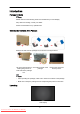
Introduction Package Contents Note Please make sure the following items are included with your LCD Display. If any items are missing, contact your dealer. Contact a local dealer to buy optional items. Checking the Contents of the Package Remove the lock from the package box, as shown in the figure above. Lift up the package box by Check the contents of the holding the grooves on package. both sides of the package box. Remove the Styrofoam and vinyl cover.
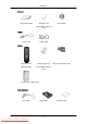
Introduction Manuals Quick Setup Guide Warranty Card User's Guide (Not available in all locations) Cables Power Cord D-Sub Cable Remote Control Batteries (AAA X 2) (BP59-00138A) (Not available in all locations) Others BNC to RCA Adaptor Jack Ferrite Core for Power Cord Sold separately DVI Cable NetworkBox 9 Downloaded From TV-Manual.
Introduction Sold separately RGB to BNC Cable BNC to BNC Cable Semi Stand KIT Ferrite Core • The ferrite cores are used to shield the cables from interference. • When connecting a cable, open the ferrite core and clip it around the cable near the plug. Your LCD Display Front MENU button [MENU] Opens the on-screen menu and exits from the menu. Also use to exit the OSD menu or return to the previous menu.
Introduction Switches from PC mode to Video mode. Selects the input source that an external device is connected to. [PC] → [DVI] → [AV] → [Component] → [HDMI] → [MagicInfo] → [BNC] Note • MagicInfo can only be enabled when a network box is connected. • The HDMI port and network box cannot be connected at the same time. PIP button Push the PIP button to turn the PIP screen On / Off. More than one PIP cannot overlap on screen as BNC and the component use the same terminal.
Introduction POWER S/W ON [ │ ] / OFF [O] Switches the LCD Display On/Off. POWER The power cord plugs into the LCD Display and the wall outlet. RS232C OUT/IN (RS232C Serial PORT) MDC(Multiple Display Control) Program Port RGB IN (PC Connection Terminal (Input)) • Use a D-Sub Cable (15 pin D-Sub) - PC mode (Analog PC) • Connect the RGB IN port on the monitor to the BNC port on the PC using the RGB to BNC cable.
Introduction DVI/RGB/HDMI AUDIO IN (PC/DVI/ HDMI Audio Connection Terminal (Input)) L] AV/COMPONENT AUDIO IN [R-AUDIO- Connect the port of the DVD, VCR (DVD / DTV Set-Top Box) to the [R-AUDIO-L] port of the LCD Display. DVI OUT • Connect a monitor to another monitor through a DVI cable. • Connect the DVI OUT port on the monitor to the HDMI IN port on the other monitor using the DVI to HDMI cable.
Introduction BNC OUT [R, G, B, H, V] (BNC Terminal (Output)) BNC (Analog PC) Connection: connecting the R, G, B, H, V ports. The number of LCD Displays that can be connected to the loopout depends on the cables, signal source, etc. With cables or signal source where there is no degradation, up to 10 LCD Displays can be connected (May not be supported depending on the connected cable).
Introduction POWER OFF Number Buttons DEL / GUIDE button + VOL SOURCE D.MENU TOOLS Up-Down Left-Right buttons INFO COLOR BUTTONS TTX/MIX MTS/DUAL ENTER/PRE-CH MUTE CH/P TV MENU RETURN EXIT MagicInfo 1. POWER Turns the product On. 2. OFF Turns the product Off. 3. Number Buttons 4. DEL ton / GUIDE but- Press to change the channel. The "-" button is used to select Digital channels. Electronic Program Guide (EPG) display. - This function does not work for this LCD Display. 5. + VOL 6.
Introduction - This function does not work for this LCD Display. 9. Up-Down Left-Right buttons Moves from one menu item to another horizontally, vertically or adjusts selected menu values. INFO Current picture information is displayed on the upper left corner of the screen. 11. COLOR BUTTONS Press to add or delete channels and to store channels to the favorite channel list in the “Channel List” menu. 10. - This function does not work for this LCD Display. 12.
Introduction 19. RETURN Returns to the previous menu. 20. EXIT Exits from the menu screen. 21. MagicInfo MagicInfo Quick Launch Button. Note MagicInfo can only be enabled when a network box is connected. Mechanical Layout Mechanical Layout Installation VESA Bracket • When installing VESA, make sure to comply with the international VESA standards. • Purchasing VESA Bracket and Installation Information : Please contact your nearest SAMSUNG Distributor to place an order.
Introduction • SAMSUNG is not responsible for any product damage or any injury caused by installation at customer's discretion. Dimensions Notice For securing the bracket on a wall, use only machine screws of 6 mm diameter and 8 to 12 mm length. Wall Bracket Installation • Contact a technician for installing the wall bracket. • SAMSUNG Electronics is not responsible for any damages to the product or harm to customers when the installation is done by the customer.
Introduction There are two hinges(left and right). Use the correct one. 2. A- Captive Screw B- Wall Bracket C- Hinge (Left) D- Hinge (Right) Before drilling into the wall, check if the length between the two locking holes at the back of the product is correct. If the length is too short or long, loosen all or some of the 4screws on the wall bracket to adjust the length. A3. Length between the two locking holes Check the installation diagram and mark the drill points on the wall. Use the 5.
Introduction To mount the product on the wall bracket The shape of the product may vary depending on the model. (The assemblies of the plastic hanger and the screw are the same) 1. Remove the 4 screws on the back of the product. 2. Insert the screw B into the plastic hanger. Notice 3. • Mount the product on the wall bracket and make sure it is properly fixed to the left and right plastic hangers. • Be careful when installing the product on the bracket as fingers can be caught in the holes.
Introduction 4. Remove safety pin (3) and insert the 4 product holders into the corresponding bracket holes (1). Then place the product(2) so that it is firmly fixed to the bracket. Make sure to re-insert and tighten the safety pin (3) to securely hold the product to the bracket. A- LCD Display B- Wall Bracket C- Wall Wall Bracket Angle Adjustment Adjust the bracket angle to -2° before installing it on the wall. 1. Fix the product to the wall bracket. 2.
Introduction Make sure to use the top center, and not the left or the right side of the product to adjust the angle. 22 Downloaded From TV-Manual.
Connections Connecting a Computer There are several ways to connect the computer to the monitor. Choose one from the following options. Using the D-sub (Analog) connector on the video card. • Connect the D-sub to the 15-pin, [RGB IN] port on the back of your LCD Display and the 15 pin D-sub Port on the computer. Using the DVI (Digital) connector on the video card. • Connect the DVI Cable to the [DVI IN] port on the back of your LCD Display and the DVI port on the computer. 18 Downloaded From TV-Manual.
Connections Using the HDMI (digital) output on the graphics card. • Connect the [HDMI IN] port on the LCD Display to the HDMI port on the PC using the HDMI cable. Note When the HDMI cable to the PC, ensure that you select HDMI from both the Source List and Edit Name before selecting PC or DVI device so that normal PC screen and sound can be outputted. Note that sound is only available when connected according to the option that follows. Using the BNC (Analog) connector on the video card.
Connections Connect the audio cable for your LCD Display to the audio port on the back of the LCD Display. Connect the power cord for your LCD Display to the power port on the back of the LCD Display. Turn on the power switch. Note • Turn on both your computer and the LCD Display. • Contact a local SAMSUNG Electronics Service Center to buy optional items. Connecting to Other devices • AV input devices such as DVD players, VCRs or camcorders as well as your computer can be connected to the LCD Display.
Connections Connecting to a Camcorder 1. Locate the AV output jacks on the camcorder. They are usually found on the side or back of the camcorder. Connect a set of audio cables between the AUDIO OUTPUT jacks on the camcorder and the [AV/COMPONENT AUDIO IN [R-AUDIO-L]] on the LCD Display . 2. Connect a video cable between the VIDEO OUTPUT jack on the camcorder and the [AV IN [VIDEO]] on the LCD Display . 3.
Connections 2. Select BNC for the Camcorder connection using the SOURCE button on the front of the LCD Display or on the remote control. Connecting Using a DVI Cable 1. Connect between the [DVI OUT] port on the LCD Display and the input port on another monitor using a DVI cable. 2. Connect between the [AUDIO OUT] port on the LCD Display and the audio input port on another monitor using a stereo cable. 3. Select DVI using the SOURCE button on the front of the LCD Display or on the remote control.
Connections Note In HDMI mode, only PCM format audio is supported. Connecting Using a DVI to HDMI Cable 1. Connect the DVI output terminal of a digital output device to the [HDMI IN] terminal of the LCD Display using a DVI to HDMI cable. 2. Connect the red and white jacks of an RCA to stereo (for PC) cable to the same colored audio output terminals of the digital output device, and connect the opposite jack to the [DVI / RGB /HDMI AUDIO IN] terminal of the LCD Display. 3.
Connections 2. Connect a Component cable between the [BNC/COMPONENT IN [R/Y, G/PB, B/PR]] port on the LCD Display and the PR, Y, PB jacks on the DVD player. Note • Select Component for the connection to a DVD player using the SOURCE button on the front of the LCD Display or on the remote control. • Then, start the DVD Player with a DVD disc inserted. • A component cable is optional. • For an explanation of Component video, consult your DVD manual. Connecting a DTV Set Top (Cable/Satellite) Box 1.
Connections Connecting to an Audio System 1. Connect a set of audio cables between the AUX L, R jacks on the AUDIO SYSTEM and [AUDIO OUT] on LCD Display. 25 Downloaded From TV-Manual.
Using the Software Monitor Driver Note When prompted by the operating system for the monitor driver, insert the CDROM included with this monitor. Driver installation is slightly different from one operating system to another. Follow the directions appropriate for the operating system you have. Prepare a blank disk and download the driver program file at the Internet web site shown here. Internet web site : http://www.samsung.com/ Installing the Monitor Driver (Automatic) 1.
Using the Software Note This monitor driver is certified by Microsoft, and installing it will not damage your system. The certified driver will be posted on Samsung Monitor homepage. http://www.samsung.com/ Installing the Monitor Driver (Manual) Microsoft® Windows Vista™‚ Operating System 1. Insert your Manual CD into your CD-ROM drive. 2. Click (Start) and "Control Panel". Then, double-click on "Appearance and Personalization". 3. Click "Personalization" and then "Display Settings". 4.
Using the Software If the message "Windows needs..." is displayed, as shown in the figure below, click "Continue". Note This monitor driver is under certifying MS logo, and this installation will not damage your system. The certified driver will be posted on Samsung Monitor homepage. 6. Click "Update Driver..." in the "Driver" tab. 7. Check the "Browse my computer for driver software" checkbox and click "Let me pick from a list of device drivers on my computer". 8. Click "Have Disk...
Using the Software 9. Select the model that matches your monitor from the list of monitor models on the screen, and click "Next". 10. Click "Close" → "Close" → "OK" → "OK" on the following screens displayed in sequence. Microsoft® Windows® XP Operating System 29 Downloaded From TV-Manual.
Using the Software 1. Insert CD into the CD-ROM drive. 2. Click "Start" → "Control Panel", then click the "Appearance and Themes" icon. 3. Click "Display" icon and choose the "Settings" tab then click "Advanced...". 4. Click the "Properties" button on the "Monitor" tab and select "Driver" tab. 5. Click "Update Driver..." and select "Install from a list or..." then click "Next" button. 6. Select "Don't search, I will...", then click "Next" and then click "Have disk". 30 Downloaded From TV-Manual.
Using the Software 7. Click the "Browse" button then choose A:(D:\Driver) and choose your monitor model in the model list and click the "Next" button. 8. If you can see the following message window, then click the "Continue Anyway" button. Then click "OK" button. Note This monitor driver is certified by Microsoft,, and this installation will not damage your system. The certified driver will be posted on Samsung Monitor homepage. http://www.samsung.com/ 9.
Using the Software 10. Monitor driver installation is completed. Microsoft® Windows® 2000 Operating System When you can see "Digital Signature Not Found" on your monitor, follow these steps. 1. Choose "OK" button on the "Insert disk" window. 2. Click the "Browse" button on the "File Needed" window. 3. Choose A:(D:\Driver), then click the "Open" button and then click "OK" button. How to install 1. Click "Start", "Setting", "Control Panel". 2. Double click the "Display" icon. 3.
Using the Software 4. Select the "Monitor" tab. 5. Click the "Change" button in the "Monitor Type" area. 6. Choose "Specify the location of the driver". 7. Choose "Display a list of all the driver in a specific location...", then click "Next" button. 8. Click the "Have Disk" button. 9. Specify A:\(D:\driver), then click "OK" button. 10. Select "Show all devices" and choose the monitor that corresponds to the one you connected to your computer and click "OK". 11.
Using the Software 10. You have finished setting up your monitor. Execute X-Window after setting other requested hardware. MDC (Multi-Display Control) Installation 1. Insert the installation CD into the CD-ROM drive. 2. Click the MDC installation file. Note If the popup window to install the software for the main screen is not displayed, proceed with the installation using the MDC executable file on the CD. 3. When the Installation Shield Wizard window appears, click "Next". 4.
Using the Software Using MDC 35 Downloaded From TV-Manual.
Introduction A Multiple Display Control (MDC) is an application allowing various displays to be easily and simultaneously operated on a PC. RS-232C, a standard of serial communication, is used for the communication between a PC and a display. Therefore, a serial cable should be connected between the serial port on a PC and the serial port on a display. Main Screen Click Start > Program > Samsung > MDC System to start the program. Select a set to see the volume of the selected set within the slider.
Main Icons Select Button Remocon Info Grid Safety Lock Display Selection Port Selection Control Tools 1. Use the main icons to switch into each screen. 2. Allows you to enable or disable the remote control signal receiving function of the display unit. 3. Set the Safety Lock function. When setting the Lock function, you can only operate power and lock buttons on the remote control and set. 4. The setting for the PC Serial Port can change. The original value is COM1. 5.
1. The Multiple Display Control is originally set to COM1. 2. If any port other than COM1 is used, COM1 through COM4 can be selected in the Port Selection Menu. 3. If the exact port name that is connected to the LCD Display using a serial cable is not selected, communication will be unavailable. 4. The selected port is stored in the program and used for the next program as well. Power Control 1. Click Power Control of the main icons and the Power Control screen appears. Downloaded From TV-Manual.
Info Grid shows some basic information necessary to Power Control. 1) (Power Status) 2) Input 3) Image Size 4) On Timer 5) Off Timer 2. Use the Select All button or Check Box to choose a display to control. Downloaded From TV-Manual.
Power Control allows controlling some of the functions of the selected display. 1) Power On/Off - Turns the power of the selected display On/Off. 2) Volume - Controls the volume level of the selected display. It receives the volume value of the selected display from the sets and displays it in the slider. (When you cancel the selection or choose Select All, the value returns to the default value 10) 3) (Mute On/Off) - Turns on/off the Mute function of the selected display.
• PC Mode Downloaded From TV-Manual.
Info Grid shows some basic information necessary to Input Source Control. 1) PC - Changes the Input Source of the selected display to PC. 2) BNC - Changes the Input Source of the selected display to BNC. 3) DVI - Changes the Input Source of the selected display to DVI. 4) TV - Changes the Input Source of the selected display to TV. 5) DTV - Changes the Input Source of the selected display to DTV. 6) AV - Changes the Input Source of the selected display to AV.
The Input Source Control feature is available only for the displays whose power status is ON. Image Size PC, BNC, DVI 1. Click Image Size of the main icons and the Image Size control screen appears. Info Grid shows some basic information necessary to Image Size Control. 1) ( Power Status) - Shows the power status of the current display. 2) Image Size - Shows the current Image Size of the display in use. 3) Input - Info Grid displays only the displays whose Input Source is PC, BNC, DVI.
Image Size TV, AV, S-Video, Component, DVI(HDCP), HDMI, DTV 1. Click Image Size of the main icons and the Image Size control screen appears. Info Grid shows some basic information necessary to Image Size Control. 1) Click the Video Source tab to adjust Image Size for TV, AV, S-Video, Component, DVI(HDCP), HDMI, DTV. Click Select All or use Check Box to select a display to control. 2) Info Grid displays only the display having TV, AV, S-Video, Component or DVI(HDCP) as input source.
1. Click Time of the main icons and the Time Control screen appears. Info Grid shows some basic information necessary to Time Control. 1) Current Time - Set the current time for the selected display (PC Time). - To change the current time, first change the PC Time. 2) On Time Setup - Set the Hour, Minute, AM/PM of On Time Setup, Status, Source, Volume of the selected display. 3) Off Time Setup - Set the Hour, Minute, and AM/PM, Status for Off Time Setup of the selected display.
PIP Size 1. Click PIP of the main icons and the PIP control screen appears. Click Select All or use Check Box to select a display to control. Info Grid shows some basic information necessary to PIP Size Control. 1) PIP Size - Shows the current PIP Size of the display in use. 2) OFF - Turns off the PIP of the selected display. 3) Large - Turns on the PIP of the selected display and changes the size to Large. 4) Small - Turns on the PIP of the selected display and changes the size to Small.
PIP PIP Source 1. Click PIP of the main icons and the PIP control screen appears. Info Grid shows some basic information necessary to PIP Source Control. 1) PIP Source - PIP Source can be controlled with turning on the LCD Display power. 2) PC - Changes the source of the PIP of the selected display to PC. 3) BNC - Changes the source of the PIP of the selected display to BNC. 4) DVI - Changes the source of the PIP of the selected display to DVI.
Settings Picture 1. Click Settings of the main icons and the Settings Control screen appears. Info Grid shows some basic information necessary to Settings Control. When each function is selected, the set value of the selected function is displayed in the slide.When selected, each function fetches the value for the set and displays it on the slide bar. When "Select All" is chosen, the default value is displayed. Changing a value in this screen will automatically change the mode to "CUSTOM.
- Adjusts the Color Tone for the selected display. 8) Color Temp - Adjusts the Color Temp for the selected display. 9) Brightness Sensor - Adjusts the Brightness Sensor for the selected display. 10) Dynamic Contrast - Adjusts the Dynamic Contrast for the selected display. The Input source of MagicInfo works only on MagicInfo model. Color Temp is only enabled if the Color Tone is set to Off. The Input source of TV works only on TV model.
2) Contrast - Adjusts Contrast of the selected display. 3) Brightness - Adjusts Brightness for the selected display. 4) Red - Adjusts red Color of the selected display. - Available only for NT. 5) Green - Adjusts green Color of the selected display. - Available only for NT. 6) Blue - Adjusts blue Color of the selected display. - Available only for NT. 7) Color Tone - Adjusts the Color Tone for the selected display. 8) Color Temp - Adjusts the Color Temp for the selected display.
Info Grid shows some basic information necessary to Settings Control. When each function is selected, the set value of the selected function is displayed in the slide. When selected, each function fetches the value for the set and displays it on the slide bar. When "Select All" is chosen, the default value is displayed. Changing a value in this screen will automatically change the mode to "CUSTOM." 1) Audio - Controls audio settings for all input sources. 2) Bass - Adjusts Bass of the selected display.
Image Lock 1. Click Settings of the main icons and the Settings Control screen appears. Info Grid shows some basic information necessary to Settings Control. 1) Image Lock - Available only for PC, BNC. 2) Coarse - Adjusts Coarse of the selected display. 3) Fine - Adjusts Fine of the selected display. 4) Position - Adjusts Position of the selected display. 5) Auto Adjustment - Self-Adjust to the incoming PC signal. The Input source of MagicInfo works only on MagicInfo model.
An "Info Grid" showing several basic data items appears. 1) Maintenance - Allows the Maintenance Control function for all input sources. 2) Auto Lamp Control - Automatically adjusts the backlight of the selected display at a specified time. The Manual Lamp Control automatically turns off if you adjust using the Auto Lamp Control. 3) Manual Lamp Control - Allows you to adjust the backlight of the selected display regardless of the time.
1) Scroll - This function is used to remove the afterimages that occur when a still screen is displayed on the selected display for a long time. 2) Pixel Shift - This allows the screen to be moved finely at the specified time interval. 3) Safety Screen - The Safety Screen function is used to prevent afterimages from occurring when a still screen is displayed on the monitor for a long time.
1. Click on the "Maintenance" icon in the Main Icon column to display the Maintenance screen. 1) Video Wall - A Video Wall is a set of video screens that are connected together, so that each screen shows a part of the whole picture or so that the same picture is repeated on each screen. 2) Video Wall (Screen divider) - The screen can be divided into. You can select a number of screens with a different layout when dividing. z Select a mode from Screen divider. z Select a display from Display Selection.
You may not operate this function in MagicInfo. The Input source of TV works only on TV model. The Maintenance Control function is available only for the displays where the power status is ON. Troubleshooting 1. The display you wish to control does not appear on the Power Control Info Grid - Check the connection of RS232C. (Check if it is properly connected to the Com1 port) - Check the displays to see if any of the other displays connected have the same ID.
2. Selected one display: Fetches and displays the settings value for the selected display. 3. Selected one display (ID1) and add another display (ID3): The program, which was displaying the settings value of ID 1, fetches and displays the value of ID3. 4. Selected all sets using Select All: Returns to the Factory Default Value. Downloaded From TV-Manual.
Adjusting the LCD Display Input Available Modes • PC / DVI / BNC • AV • Component • HDMI • MagicInfo Note • MagicInfo can only be enabled when a network box is connected. • The HDMI port and network box cannot be connected at the same time. Source List MENU → ENTER → → ENTER → A network box is not connected → , A network box is connected → ENTER Use to select PC, DVI or other external input sources connected to the LCD Display. Use to select the screen of your choice. 1. PC 2. DVI 3.
Adjusting the LCD Display PIP Note Available Modes: PIP ON Note The PIP function is not available when Video Wall is On. When external AV devices such as VCRs or DVDs are connected to the LCD Display , PIP allows you to watch video from those devices in a small window super-imposed on the PC Video signal. (Off/On) MENU → ENTER → → → ENTER → Note • More than one PIP cannot be overlapped on screen as BNC and the Component use the same terminal.
Adjusting the LCD Display • PC : DVI / AV / Component / HDMI • BNC : DVI / AV / HDMI • DVI / AV : PC / BNC • Component : PC • HDMI : PC / BNC Swap MENU → ENTER → → →ENTER → → → →ENTER → Swaps the contents of the PIP and main image. The image in the PIP window will appear on the main screen, and the main screen image will appear in the PIP window. Size MENU → ENTER → → , → →ENTER → → → → → ENTER → → ENTER Changes the Size of the PIP window.
Adjusting the LCD Display Changes the Position of the PIP window. Transparency MENU → ENTER → → , → → ENTER → → → → → → → ENTER → → ENTER Adjusts the Transparency of PIP windows. • High • Medium • Low • Opaque Note • PIP turns off when the LCD Display is switched to an external source. • For PC and DVI, this is deactivated if the cable is disconnected.
Adjusting the LCD Display are common signals for AV and PC, make sure to set the Edit Name in accordance with the input signal. • The Picture menu changes depending on the input signal and Edit Name. Picture [PC / DVI / BNC / MagicInfo Mode] Available Modes • PC / DVI / BNC • AV • Component • HDMI • MagicInfo Note • MagicInfo can only be enabled when a network box is connected. • The HDMI port and network box cannot be connected at the same time.
Adjusting the LCD Display For documents or works involving heavy text. 4. Custom Although the values are carefully chosen by our engineers, the pre-configured values may not be comfortable to your eyes depending on your taste. If this is the case, adjust the brightness and contrast by using the OSD menu. Custom By using the on-screen menus, the contrast and brightness can be changed to your personal preference. MENU → → ENTER → → → ENTER → (Not available when Dynamic Contrast is set to On.
Adjusting the LCD Display → , → ENTER The color tones can be changed. (Not available when Dynamic Contrast is set to On.) 1. Off 2. Cool 3. Normal 4. Warm 5. Custom Note If you set the Color Tone to Cool, Normal, Warm, or Custom, the Color Temp. function is disabled. If you set the Color Tone to Off, the Color Control function is disabled Color Control Adjusts individual Red, Green, Blue color balance. MENU → → ENTER → → → → → ENTER → (Not available when Dynamic Contrast is set to On.
Adjusting the LCD Display → , 3. → ENTER Blue MENU → → ENTER → → ENTER → → , → → → → ENTER → → → → → ENTER → → → → ENTER Color Temp. MENU → → , → ENTER → → → ENTER Color Temp. is a measure of the 'warmth' of the image colors. (Not available when Dynamic Contrast is set to On.) Note This function is only enabled if the Color Tone is set to Off. Image Lock Image Lock is used to fine-tune and get the best image by removing noise that creates unstable images with jitters and shakiness.
Adjusting the LCD Display → , → ENTER Removes noise such as horizontal stripes. If the noise persists even after Fine tuning, repeat it after adjusting the frequency (clock speed). Position MENU → → ENTER → → → ENTER → → , , , → → → ENTER → → → → → → ENTER Adjusts the screen location horizontally and vertically. Auto Adjustment MENU → → ENTER → → → → → → → → ENTER → The values of Fine, Coarse, Position are adjusted automatically.
Adjusting the LCD Display → , → ENTER Selects either On or Off with the signal control. Signal Control MENU → → ENTER → → ENTER → → 1. R-Gain MENU → → , 2. → → → → → → ENTER → → ENTER → → ENTER → → ENTER → → → → → → → → → → → ENTER→ → ENTER → → → → → → → → ENTER → → → → ENTER→ → → → → → → B-Gain → , → ENTER → → ENTER → → → → ENTER R-Offset MENU → → , → ENTER → → ENTER → → → → → → → → → → ENTER → → ENTER→ → ENTER G-Offset MENU → → , 6. → → ENTER MENU → 5.
Adjusting the LCD Display MENU → → ENTER → → ENTER → → → → → → → → → → ENTER → → → → → → → ENTER → → , → ENTER Size MENU → → , → ENTER → → → → → → → → → → ENTER → → ENTER The Size can be switched. 1. 16:9 2. 4:3 HDMI Black Level MENU → → , → ENTER → → → → → → → → ENTER → → ENTER When watching with a DVD or set-top box connecting to the product via HDMI or DVI, image quality deterioration (black level, lower-quality contrast, lighter color tone, etc.
Adjusting the LCD Display PIP Picture MENU → → , → ENTER → → → → → → → → → → → ENTER → → → → → → → → → → → ENTER → ENTER Adjusts the PIP Screen Settings. Note • 1. Available Modes: PIP ON Contrast MENU → → → , → ENTER → → ENTER→ → ENTER Adjusts the Contrast of the PIP window on the screen. 2. Brightness MENU → → → , → ENTER → → → ENTER → → → → → → → → → → → ENTER → ENTER Adjusts the Brightness of the PIP window on the screen. 3.
Adjusting the LCD Display Note This function is not available if PC signal is received while in DVI or HDMI mode. 5. Tint MENU → → → , → ENTER → → → → → → → → → ENTER → → → → → → → → ENTER → ENTER Adds a natural tone to the PIP window. Note This function is not available if PC signal is received while in DVI or HDMI mode.
Adjusting the LCD Display Brightness Sensor MENU → → ENTER → ENTER → → , → → → → → → → → → → → → → → ENTER Brightness Sensor automatically detects distribution of the inputted visual signal and adjusts to create optimum brightness. 1. Off 2. On Picture [ AV / HDMI / Component Mode] Available Modes • PC / DVI / BNC • AV • Component • HDMI • MagicInfo Note • MagicInfo can only be enabled when a network box is connected.
Adjusting the LCD Display Dynamic, Standard, Movie, or Custom can be activated. (Not available when Dynamic Contrast is set to On.) 1. Dynamic 2. Standard 3. Movie 4. Custom Custom By using the on-screen menus, the contrast and brightness can be changed to your personal preference. MENU → → ENTER → → ENTER → → (Not available when Dynamic Contrast is set to On.) Contrast MENU → → , → ENTER → → ENTER → → → ENTER→ → ENTER Adjusts the Contrast.
Adjusting the LCD Display → , → ENTER Adjusts the picture Color. Tint MENU → → → , → ENTER → → → ENTER → → → → → → → → ENTER → ENTER Adds a natural tone to the display. Color Tone MENU → , → → ENTER → → ENTER → → ENTER The color tones can be changed. The individual Color components are also user adjustable. (Not available when Dynamic Contrast is set to On.) 1. Off 2. Cool2 3. Cool1 4. Normal 5. Warm1 6.
Adjusting the LCD Display (Not available when Dynamic Contrast is set to On.) Note This function is only enabled if the Color Tone is set to Off. Size MENU → → , → ENTER → → → → → → ENTER → → ENTER The Size can be switched. 1. 16:9: Sets the picture to 16:9 wide mode. 2. Zoom 1: Magnifies the size of the picture on the screen. 3. Zoom 2: Magnifies the size of the picture more than Zoom 1. 4. 4:3: Sets the picture to 4:3 normal mode. 5.
Adjusting the LCD Display 1. Off 2. On Note Digital NR function is not available for all resolutions. HDMI Black Level MENU → → , → ENTER → → → → → → → → ENTER → → ENTER When a DVD or set-top box is connected to your TV via HDMI or DVI, it may cause a degradation in the screen quality, such as an increase in the black level, a low contrast, or discoloration, etc., depending on the external device connected.
Adjusting the LCD Display 1. Off 2. On PIP Picture MENU → → , → ENTER → → → → → → → → → → ENTER → → ENTER Adjusts the PIP Screen Settings. Note • 1. Available Modes: PIP ON Contrast MENU → → , → ENTER → → ENTER→ → → → → → → → → → ENTER → → → → → → ENTER → → → → → ENTER → → ENTER Adjusts the Contrast of the PIP window on the screen. 2. Brightness MENU → → , → ENTER → → → ENTER→ → → → → → ENTER Adjusts the Brightness of the PIP window on the screen. 3.
Adjusting the LCD Display , → → ENTER Dynamic Contrast automatically detects the distribution of the visual signal and adjusts to create an optimum contrast. 1. Off 2. On (Disabled when PIP is set to On.) Lamp Control MENU → → → , → ENTER → → → → → → → → → → → → ENTER → ENTER Adjusts the inverter lamp in order to reduce energy consumption. Note This function does not operate when Dynamic Contrast is set to On in PC, DVI, AV, HDMI, Component or MagicInfo modes.
Adjusting the LCD Display Auto Motion Plus 120Hz MENU → → ENTER → [Picture] → ENTER → [Auto Motion Plus 120Hz] → , → → → → → → → → → → → → → ENTER This feature can be used to view fast moving scenes. 1. Mode MENU → → ENTER → [Picture] → → → → → → → → → → → → → ENTER → [Auto Motion Plus 120Hz] → ENTER → [Mode] → , 2. → ENTER • Off : switches Auto Motion Plus 120Hz off. • Clear : sets Auto Motion Plus 120Hz to Clear (suitable for viewing moving images clearly) mode.
Adjusting the LCD Display Judder : use to reduce the judder as much as you want. Note Only activated when Mode is set to Custom. Sound Available Modes • PC / DVI / BNC • AV • Component • HDMI • MagicInfo Note • MagicInfo can only be enabled when a network box is connected. • The HDMI port and network box cannot be connected at the same time. Mode MENU → → , → → ENTER → → ENTER → → ENTER The LCD Display has a built-in high fidelity stereo amplifier. 1.
Adjusting the LCD Display Selects Custom if you want to adjust the settings according to your personal preferences. Custom The sound settings can be adjusted to suit your personal preferences. MENU → → → ENTER → → → ENTER → Note • You can hear the sound even when sound value is set to 0. • If you adjust sound using Custom function, Mode will turn to Custom mode. Bass MENU → → , → → ENTER → → → ENTER → →ENTER→ → ENTER Emphasizes low frequency audio.
Adjusting the LCD Display Reduces the difference in volume control between broadcasters. 1. Off 2. On SRS TS XT MENU → → , → → ENTER → → → → → ENTER → → ENTER SRS TS XT is a patented SRS technology that solves the problem of playing 5.1 multichannel content over two speakers. TruSurround XT delivers a compelling, virtual surround sound experience through any two-speaker playback system, including internal television speakers. It is fully compatible with all multichannel formats. 1. Off 2.
Adjusting the LCD Display → , → ENTER When you use the product with it connecting to a Home theater, turn the Internal speakers off so you can listen to sound from the Home theater's (external) speakers. 1. Internal Sound is outputted both from the Internal speaker and the External speakers, but the volume control is only available from the Internal speaker. 2. External When sound is only outputted from the External speakers, the volume control is also only available from the External speakers.
Adjusting the LCD Display You can choose one of 13 languages. Note The language chosen affects only the language of the OSD. It has no effect on any software running on the computer. Time Selects from one of 4 time settings, Clock Set, Sleep Timer, On Timer, and Off Timer. MENU → → → → ENTER → → → ENTER → Clock Set MENU → → , → , → → → ENTER → → → ENTER → → ENTER→ → ENTER Current Time Setting.
Adjusting the LCD Display 5. 120 6. 150 7. 180 On Timer MENU → → , / , → → → ENTER → → → ENTER → → → → ENTER→ → ENTER Turns the LCD Display on automatically at a preset time. Controls the mode and the volume level at the time the LCD Display turns on automatically. Off Timer MENU → → → , / , → → → ENTER → → → ENTER → → ENTER Turns the LCD Display off automatically at a preset time.
Adjusting the LCD Display 1. High 2. Medium 3. Low 4. Opaque Safety Lock Change PIN MENU → → → → ENTER → → → → → → ENTER → → ENTER → [0∼9] → [0∼9] → [0∼9] → [0∼9] The password can be changed. Note The preset password for the LCD Display is "0000". Lock On MENU → → → → ENTER → ENTER → → → → → ENTER → → → → [0∼9] → [0∼9] → [0∼9] → [0∼9] This is the function that locks the OSD in order to keep the current settings or to prevent others from adjusting the settings.
Adjusting the LCD Display → , → ENTER This feature adjusts the power consumption of the unit in order to save energy. 1. Off 2. On Video Wall A Video Wall is a set of video screens connected together, so that each screen shows a part of the whole picture or where the same picture is repeated on each screen. When the Video Wall is on, you can adjust the Video Wall screen setting.
Adjusting the LCD Display The Format can be selected to see a divided screen. 1. Full Provides a full screen without any margins. 2. Natural Displays a natural image with the original aspect ratio intact. Horizontal MENU → → → → ENTER → → → → ENTER → → , → → → → → → → ENTER → → ENTER Sets how many parts the screen should be divided horizontally. Five adjustment levels: 1, 2, 3, 4, and 5.
Adjusting the LCD Display The screen can be divided into several images. A number of screens can be selected with a different layout when dividing. • Select a mode in Screen Divider. • Select a display in Display Selection. • The selection will be set up by pressing a number in the selected mode. Safety Screen The Safety Screen function is used to prevent afterimages that may appear when a still picture is displayed on the screen over a long time.
Adjusting the LCD Display Sets how many pixels the screen moves horizontally. Five adjustment levels: 0, 1, 2, 3, and 4. Vertical MENU → → → → ENTER → → ENTER → → → → ENTER → → , → ENTER → → → → → → → → → → ENTER → → → ENTER → → , → ENTER → → → → → → → → ENTER → Sets how many pixels the screen moves vertically. Five adjustment levels: 0, 1, 2, 3, and 4. Time MENU → → → → ENTER → → ENTER → Set the time interval for performing the horizontal or vertical movement, respectively.
Adjusting the LCD Display You can set the timer for Screen Burn Protection. If you start the operation to erase any residual image, the operation will be performed for the set period of time and then automatically finish. 1. Off 2. On Mode MENU → → → → ENTER → → → ENTER → → → → → → → ENTER → → → → → → → → → → ENTER → → → → ENTER → → , → ENTER You can change the Safety Screen Type. 1. Scroll 2. Bar 3.
Adjusting the LCD Display Time MENU → → → → ENTER → → → ENTER → → → → → → → → → → → ENTER → → → ENTER → → , → ENTER Within the set period of time specify a time for execution. • Mode-Scroll : 1~5 sec • Mode-Bar, Eraser : 10~50 sec Scroll MENU → → → → ENTER → → → → ENTER → → → → → → → → → ENTER → This function helps to remove after-images on the screen by moving all the pixels on the LCD according to a pattern.
Adjusting the LCD Display Eraser MENU → → → → ENTER → → → → → → → → → →ENTER → → → → → ENTER → This function prevents after-images on the screen by moving a rectangular pattern. Side Gray MENU → → , → → → ENTER → → → → → → → → → → →ENTER → → → → → ENTER → → ENTER Select the brightness of the grey for the screen background. 1. Off 2. Light 3.
Adjusting the LCD Display Note Available in PC mode only 1. Off 2. 1024 X 768 3. 1280 X 768 4. 1360 x 768 5. 1366 X 768 Note Selecting the menu is only allowed when the graphics resolution is set to 1024 x 768 @ 60Hz, 1280 x 768 @ 60Hz, 1360 x 768 @ 60Hz or 1366 x 768 @ 60Hz. Power On Adjustment MENU → → → , → → → ENTER → → → → → → → → → → → ENTER → ENTER Adjusts the Power On time for the screen. Caution: Set the Power On time to be longer to avoid overvoltage.
Adjusting the LCD Display 1. Landscape 2. Portrait Reset Reverts the product settings to factory defaults. The Reset function is only available when PC / DVI is being used. MENU → → → → ENTER → → ENTER → → → → → → → → → → → → → → → → → → → → → → → → → → → → → → Image Reset MENU → → → → ENTER → → ENTER → → ENTER → → , → ENTER Note Available in PC mode only Note The Reset function is not available when Video Wall is On.
Adjusting the LCD Display • Component • HDMI • MagicInfo Note • MagicInfo can only be enabled when a network box is connected. • The HDMI port and network box cannot be connected at the same time. Multi Control Assigns an individual ID to the SET. MENU → → • , → → → → ENTER → → ENTER → [0~9] ID Setup Assigns distinctive IDs to the SET. • ID Input Use to select the transmitter functions of the individual SET. Only a SET where the ID corresponds to the transmitter setting becomes activated.
Adjusting the LCD Display Note • The remote control can be used to select MagicInfo. However, it is recommended to use a separate USB keyboard to utilize MagicInfo fully. • For MagicInfo in Device mode, moving external devices while booting may cause errors. Set up external devices only if the LCD Display turns on. • Do not unplug the LAN cable used for the network (ex: video display). Otherwise, the program (MagicInfo) may stop. If you do unplug the cable, restart the system.
Adjusting the LCD Display You can select an Application to be executed in your computer when Windows starts. 2. Select TCP/IP - step 2 In step 2 of MagicInfo Setup Wizard, you don’t have to go to Network Setting on the desktop to make your settings for TCP/IP. You just do that at step 2 of MagicInfo installation. 3. Select Language - step 3 75 Downloaded From TV-Manual.
Adjusting the LCD Display When using multiple languages, you can choose and set a specific language among them. 4. Select Screen Type - step 4 You can select which rotation type will be applied to your device. 5. Setup Information 76 Downloaded From TV-Manual.
Adjusting the LCD Display Shows the settings that have been selected by the user. Note If the MagicInfo icon is not displayed on the notification area, double click the MagicInfo icon on the window desktop. The icon will appear. 77 Downloaded From TV-Manual.
Troubleshooting Self-Test Feature Check Note Check the following items yourself before calling for assistance. Contact a Service Center for problems that you cannot solve by yourself. Self-Test Feature Check 1. Turn off both your computer and the LCD Display. 2. Unplug the video cable from the back of the computer. 3. Turn on the LCD Display.
Troubleshooting • Do not use benzene, thinner or other flammable substances. 2) Maintaining the Flat Panel Display Screen. Clean with a soft cloth (cotton flannel). • Never use acetone, benzene or thinner. (They may cause flaws or deformation of the screen surface.) • The user is responsible for any damage caused by using these substances. Symptoms and Recommended Actions Note A LCD Display recreates visual signals received from the computer.
Troubleshooting A: Check if the signal cable between the computer and the LCD Display is securely connected. (Refer to Connecting a Computer) Problems related to the Screen Note Problems related to the LCD Display screen and their solutions are listed. Q: The screen is blank and the power indicator is off. A: Ensure that the power cord is firmly connected and the LCD Display is on. (Refer to the Connecting a Computer) Q: "Check Signal Cable" message.
Troubleshooting Q: The screen color is inconsistent. A: Adjust color using Custom under OSD Color Adjustment menu. Q: The color image is distorted by dark shadows. A: Adjust color using Custom under OSD Color Adjustment menu. Q: The color white is poor. A: Adjust color using Custom under OSD Color Adjustment menu. Q: The Power Indicator blinks. A: The LCD Display is currently saving the changes made in the settings to the OSD memory.
Troubleshooting A: Check if the batteries are empty. A: Check if the power is on. A: Check if the power cord is securely connected. A: Check if a special fluorescent or neon lamp is on in the vicinity. Q: How can I change the frequency? A: The frequency can be changed by reconfiguring the video card. Q&A Note That video card support can vary, depending on the version of the driver used. (Refer to the computer or the video card manual for details.
Troubleshooting Note Before calling for assistance, check the information in this section to see if you can remedy any problems yourself. If you do need assistance, please call the phone number on the Information section or contact your dealer. 83 Downloaded From TV-Manual.
Specifications General General Model Name SyncMaster 650MP, 650FP LCD Panel Size 65 " Diagonal (163 cm) Display area 1428.48 mm (H) x 803.52 mm (V) Pixel Pitch 0.744 mm (H) x 0.744 mm (V) Synchronization Horizontal 30 ~ 81 kHz Vertical 50 ~ 85 Hz Display Color 16.7 M Resolution Optimum resolu- 1920 x 1080 @ 60 Hz (RB) tion Maximum resolu- 1920 x 1080 @ 60 Hz (RB) tion Input Signal, Terminated RGB Analog, DVI(Digital Visual Interface) Compliant Digital RGB 0.
Specifications Dimensions (W x H x D) / Weight 1554.0 x 1029.0 x 500.0 mm / 61.2 x 40.5 x 19.7 inch (With Stand) / 69.0 Kg / 152.1 lbs VESA Mounting Interface 800 x 400 mm Environmental considerations Temperature : 32°F ~ 104°F (0°C ~ 40°C) Operating Humidity : 10 % ~ 80 %, non-condensing Storage Temperature : -4°F ~ 113°F (-20°C ~ 45°C) Humidity : 5 % ~ 95 %, non-condensing Plug and Play Capability This LCD Display can be installed on any Plug & Play compatible system.
Specifications Preset Timing Modes If the signal transferred from the computer is the same as the following Preset Timing Modes, the screen will be adjusted automatically. However, if the signal differs, the screen may go blank while the power LED is on. Refer to the video card manual and adjusts the screen as follows. Display Mode Horizontal Frequency (kHz) IBM, 640 x 350 31.469 70.086 25.175 +/- IBM, 640 x 480 31.469 59.940 25.175 -/- IBM, 720 x 400 31.469 70.087 28.
Specifications called the Vertical Frequency or Refresh Rate. Unit: Hz 87 Downloaded From TV-Manual.
Information For a Better Display Adjust the computer resolution and screen injection rate (refresh rate) on the computer as described below to enjoy the best picture quality. You can have an uneven picture quality on screen if the best picture quality is not provided for TFTLCD. • Resolution: 1920 x 1080 • Vertical frequency (refresh rate): 60 Hz TFT-LCD panels manufactured by using advanced semiconductor technology with a precision of 1ppm (one millionth) and above is used for this product.
Information Power Off, Screen Saver, or Power Save Mode • Turn the power off for 4 hours after 20 hours in use • Turn the power off for 2 hours after 12 hours in use • Set the Monitor to power off with the PC Display Properties Power Scheme. • Use a Screen saver if possible - Screen saver in one color or a moving image is recommended. Change the Color Information periodically Note Use Two different colors Rotate the Color Information with 2 different colors every 30 minutes.
Information • Avoid using a combination of characters and background color with large difference in luminance. Avoid using Grey colors, which can cause Image retention easily. Avoid: Colors with big difference in luminance (Black & White, Grey) Change the characters color periodically • Use Bright colors with little difference in luminance. - Cycle : Change the characters color and background color every 30 minutes • Every 30 minutes, change the characters with movement.
Information • Time Period : 1 ~ 5 seconds ( Recommend : 5 ) Apply the Screen Pixel function on Product • Apply the Screen Pixel function - Symptom: Dot with Black Color move up and down. - Select method • • Instruction Guide : OSD Menu -> Set Up -> Safety Screen -> Pixel • Time Interval : 1 ~ 10 hours ( Recommend : 1 ) • Time Period : 10 ~ 50 seconds ( Recommend : 50 ) Apply the Screen Bar function - Symptom: Horizontal / Vertical Bar with Black Color move up and down.
Information • Time Interval : 1 ~ 10 hours ( Recommend : 1 ) • Time Period : 10 ~ 50 seconds ( Recommend : 50 ) 92 Downloaded From TV-Manual.
Appendix Contact SAMSUNG WORLDWIDE Note If you have any questions or comments relating to Samsung products, please contact the SAMSUNG customer care center. North America U.S.A 1-800-SAMSUNG(726-7864) http://www.samsung.com/us CANADA 1-800-SAMSUNG(726-7864) http://www.samsung.com/ca MEXICO 01-800-SAMSUNG (726-7864) http://www.samsung.com/mx Latin America ARGENTINA 0800-333-3733 http://www.samsung.com/ar BRAZIL 0800-124-421 http://www.samsung.
Appendix Europe BELGIUM 02 201 2418 http://www.samsung.com/be (Dutch) http://www.samsung.com/ be_fr (French) CZECH REPUBLIC 800 (800-726786) SAMSUNG http://www.samsung.com/cz DENMARK 8 - SAMSUNG (7267864) http://www.samsung.com/dk EIRE 0818 717 100 http://www.samsung.com/ie FINLAND 30 - 6227 515 http://www.samsung.com/fi FRANCE 01 4863 0000 http://www.samsung.com/fr GERMANY 01805 SAMSUNG http://www.samsung.de (7267864, € 0.14/Min) HUNGARY 06-80-SAMSUNG (726-7864) http://www.samsung.
Appendix CIS http://www.samsung.com/ ua_ru UZBEKISTAN 8-10-800-500-55-500 http://www.samsung.com/ kz_ru Asia Pacific AUSTRALIA 1300 362 603 http://www.samsung.com/au CHINA 400-810-5858 http://www.samsung.com/cn 010-6475 1880 HONG KONG 3698 - 4698 http://www.samsung.com/hk http://www.samsung.com/ hk_en/ INDIA 3030 8282 http://www.samsung.com/in 1-800-3000-8282 1800 110011 INDONESIA 0800-112-8888 http://www.samsung.com/id JAPAN 0120-327-527 http://www.samsung.
Appendix Vertical Frequency The screen must be redrawn several times per second in order to create and display an image for the user. The frequency of this repetition per second is called the Vertical Frequency or Refresh Rate. Unit: Hz Example: If the same light repeats itself 60 times per second, this is regarded as 60 Hz. Horizontal Frequency The time to scan one line connecting the right edge to the left edge of the screen horizontally is called the Horizontal Cycle.
Appendix Correct disposal of batteries in this product - Europe only (Applicable in the European Union and other European countries with separate battery return systems.) This marking on the battery, manual or packaging indicates that the batteries in this product should not be disposed of with other household waste at the end of their working life. Where marked, the chemical symbols Hg, Cd or Pb indicate that the battery contains mercury, cadmium or lead above the reference levels in EC Directive 2006/66.